
# Application
This article will detail how to update the AT application firmware; how to implement the working mode switching; how to open the different working modes of the module's WiFi function; and how to establish a Socket connection and communication.
#1.AT firmware update by serial port
Update method: Enter Bootloader mode, enter command 1 and download through the user serial port.
#1) Hardware preperation
First, you need to have a hardware environment in which the module can run normally. It can be any of the following:
MiCOKit or MXKit-xxxx development board,among them:
- The current MiCOKit support module includes:EMW3165,3166,3239,3031,3081。
- MXKit support module includes:EMW3080,3060,110,3090,3290。
Or the minimum working circuit of your own EMWxxx module (including at least: power, serial port, and reset button functions. If you need to burn through the serial port, you need to solve the boot mode status button: BOOT, Status two).
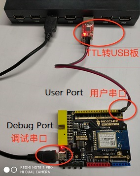
The connection diagram and port are as follows:
- (1)MiCOKit-xxx,
The ports in Device Manager are as follows:
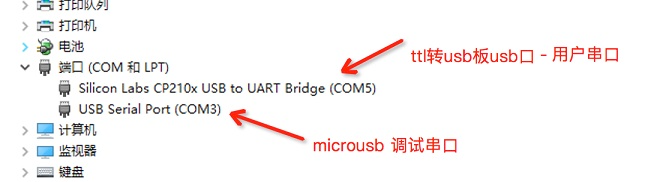
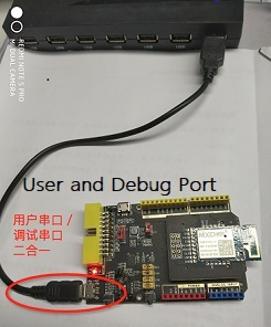
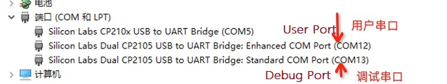
- (2)If it is MXKit-xxx, the user serial port and the debug serial port are combined. (Note: the short connector of RXD and TXD should be plugged in.)
The ports in Device Manager are as follows:
Note: To use the Arduino user serial port of the MXKit development board, you need to unplug the short connector of RXD and TXD, and need to connect ttl to usb small board. For specific usage and port number display, please refer to MiCOKit.
#2) Software preparation
- (1) Corresponds to the AT firmware of the WiFi module, for example: EMW3xxx_0000.xxxx.xxxx_ota.bin.
- (2) Firmware download software: SecureCRT (opens new window).
- (3) AT command serial debugging software: Gersey bonfire (opens new window).
- (4)) Here is a Geshe Bonfire bsp project file that integrates the basic AT command: 📎at_v2.0_cmd.bsp.zipcan be downloaded directly.
- (5) Simultaneously provide FOG cloud connection via MQTT protocol. Related AT instruction: 📎at_cmd_fog_mqtt.bsp.zip. And AWS Amazon Cloud 📎at_cmd_aws_mqtt.bsp.zip.
- (6) Each demo sample instruction set bsp project in this document can be downloaded: 📎at_all_demo.bsp.zip
#3) Update step
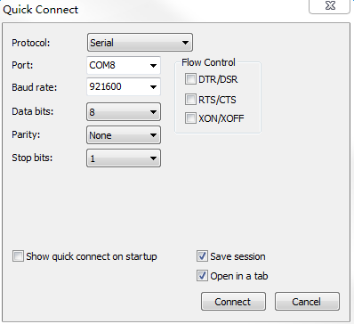
#(1) Connecting serial port
Connect the debug serial port of the development board and the user serial port to the PC through the microusb line or ttl to the usb board.
In the PC's Control Panel - Device Manager finds the COM port number, opens secureCRT, creates the connection, and configures it as follows:
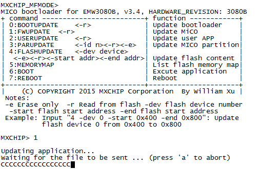
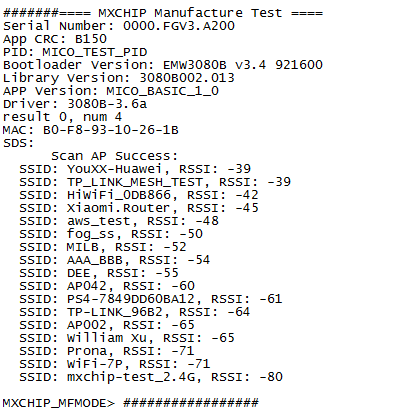
#(2) Enter Bootloader mode
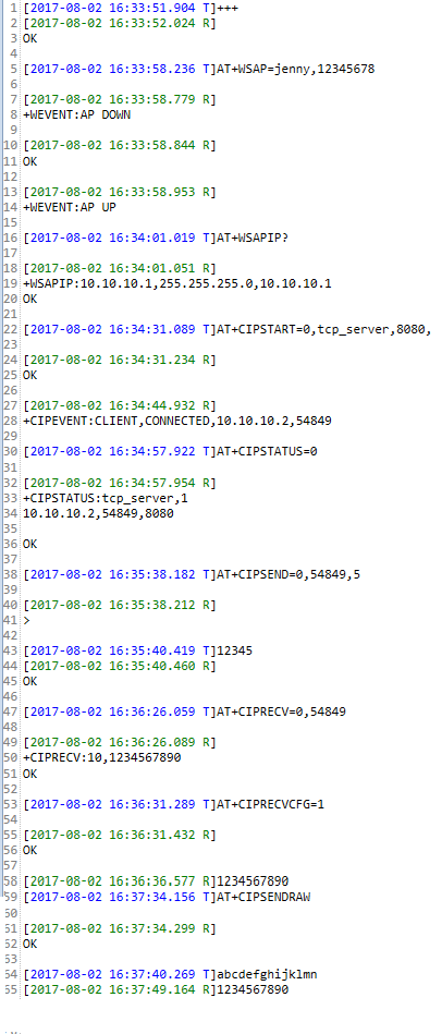
BOOT pin pulls low 0, STATUS pin pulls high 1, RESET pulls low, restarts the module, serial output log as shown below:

#(3)Download firmware
Input:1,Update application. Return as shown below:
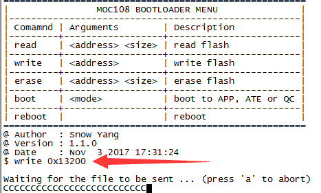
In particular, the Model 3060 module needs to be programmed using the dedicated instructions in boot mode, as shown below.:
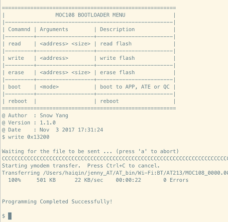
At this point, select the menu bar: Transfer - Send Ymodem, select the ota.bin firmware to add in the download list,and choose OK, as shown below:

After the download is successful, the output is as follows。
Can enter QC mode, user serial port view burning firmware version result:
Method to entry QC mode :
- One is BOOT pin to pull low, STATUS is low, reset, baud rate:921600bps。 (such as EMW3060,3165,3166,3239,3031, etc.)
- One is the user serial port input #, Reset, baud rate:921600bps。(such as: EMW3080)
QC log as below:
At this time, the BOOT pin can be pulled high, the STATUS pin is pulled high, and then reset to enter the normal working mode, that is, the AT command mode or the data transparent transmission mode.
#2.Working mode switching
#1) AT command mode to transparent mode
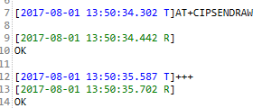
In the AT command mode, the user serial input command: AT+CIPSENDRAW\r, return: OK, you can exit the AT command mode and enter the data transparent transmission mode.
#2) Transmit mode to AT command mode
In the transparent transmission mode, the user serial input command: +++, return: OK, you can exit the transparent transmission mode and enter the AT command mode.
Specific command input, as shown below.
#3.WiFi function use case
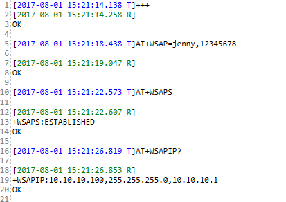
#1) Start AP mode
In the AT command mode, enter the following command through the “user serial port” to enable the module to start the Soft_AP mode. The steps are as follows:
Order | Step | Send instruction (or operation) | Return (or phenomenon) |
1 | Enter AT Command Mode | +++ | OK |
2 | Set module Soft_AP name and start | AT+WSAP=jenny,12345678\r | OK |
3 | Query whether Soft_AP was successfully created | AT+WSAPS\r | +WSAPS:ESTABLISHED\r\nOK |
4 | Query Module IP Address | AT+WSAPIP?\r | WSAPIP:10.10.10.100,255.255.255.0,10.10.10.1 |
AP mode setting serial port tool log output as shown below:
#2) Start STATION mode
In the AT command mode, enter the following command through the “user serial port” to enable the module to start the STATION mode. The steps are as follows:
Order | Step | Send instruction (or operation) | Return (or phenomenon) |
1 | Set AP name and password for module access | AT+WJAP=SWYANG,yangbatian2015\r | OK |
2 | Query if the AP is successfully connected | AT+WJAPS\r | +WJAPS:CONNECTED\r\nOK |
3 | View module's IP address | AT+WJAPIP?\r | +WJAPIP:192.168.31.67,255.255.255.0,192.168.31.1 |
The station mode sets the serial port log output as shown below:

#4.OTA function
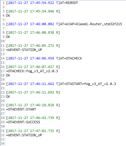
To enter the AT command mode, the device must first connect to the AP to ensure networked communication, and then perform an online firmware update by sending OTA queries and updated AT commands. The specific steps and instructions are as follows:
Order | Step | Send instruction (or operation) | Return (or phenomenon) |
1 | Enter AT Command Mode | +++ | OK |
2 | Startup Module | AT+REBOOT\r | OK |
3 | Set module STATION mode, and access AP information | AT+WJAP=Xiaomi.Router, stm32f215\r | OK,+WEVENT:STATION_UP |
4 | Query cloud updateable AT firmware version | AT+OTACHECK\r | +OTACHECK:fog_v3_AT_v2.0.3, OK |
5 | Start to update the AT firmware with the specified version number | AT+OTASTART=fog_v3_AT_v2.0.3 | OK, and then the notification message: +OTAEVENT:START , +OTAEVENT:SUCCESS, then restart, appears: +WEVENT: STATION_UP. |
The specific steps refer to the following figure:
#5.Socket communication use case
#1) TCP server side
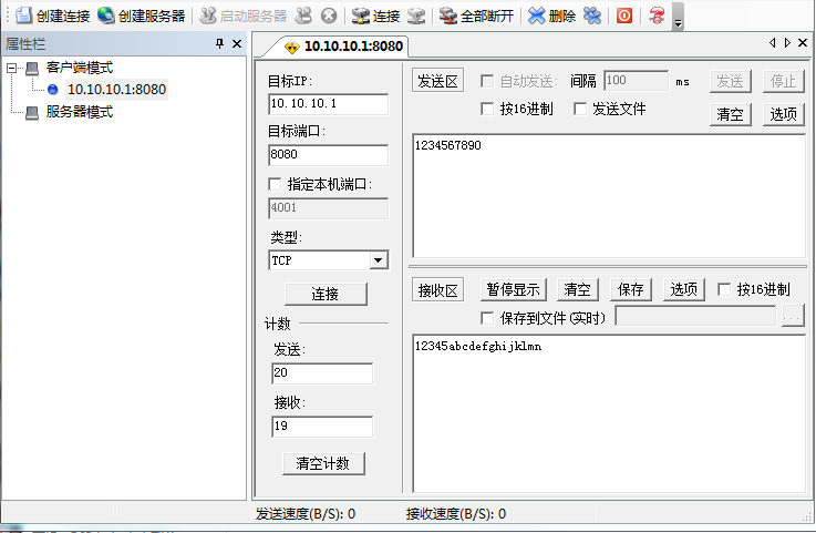
#(1) In AP mode, the module is a TCP server.
The module acts as a TCP server in Soft_AP mode and establishes a TCP connection and communication with the TCP client on the PC side. Proceed as follows:
Order | Step | Send instruction (or operation) | Return (or phenomenon) |
1 | Set and turn on Soft_AP mode | AT+WSAP=jenny,12345678\r | OK |
2 | Query Module IP Address | AT+WSAPIP?\r | +WSAPIP=10.10.10.1,255.255.255.0,10.10.10.1 |
3 | PC Connect to the module-initiated AP | PC-side Wlan list to find AP:jenny, and connect | Successful connection |
4 | Setup module to do TCP Server | AT+CIPSTART=0,tcp_server,8080\r | OK |
5 | PC from TCP client and connection | Target IP: 10.10.10.1, destination port: 8080, no local port specified | connection succeeded. +CIPEVENT=CLIENT,CONNECTED,10.10.10.2,54849 |
6 | AT command mode, the module sends data to the TCP client through the serial port | AT+CIPSEND=0,54849,5\r12345 | TCP client receiving area received: 12345 |
7 | AT command mode, TCP client sends data to the module serial port | 1. TCP tool send area sends: 1234567890 | Send successfully |
2. If the module is not automatically received to the serial port, ie: AT+CIPRECVCFG is set to 0, you need to enter the command: AT+CIPRECV=0,54849\r for data reception | +CIPRECV: 10,1234567890\r\nOK | ||
3. If the module is automatically received to the serial port, ie: AT+CIPRECVCFG is set to 1, no input command is required for data reception. | Module serial port received: 1234567890 | ||
8 | In transparent mode, the module sends data to the TCP client through the serial port | 1. Module serial input command: AT+CIPSENDRAW\r; | OK |
2. Serial input: abcdefghijklmn | PC-side TCP client received: abcdefghijklmn | ||
9 | Transparent mode, TCP client sends data to module serial port | TCP client send area input data: 1234567890 | Module serial port received: 1234567890 |
The PC uses the TCP/UDP test software to create a TCP client, as shown below.:

The TCP/UDP test software workspace is as follows:
The data receiving work area information of the serial port debugging software is as follows:
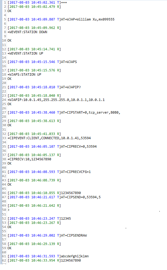
#(2) In STATION mode, the module is a TCP server.
The module is in the STATION mode, acts as a TCP server, and establishes a TCP connection, and communicates. Specific steps are as follows:
Order | Step | Send instruction (or operation) | Return (or phenomenon) |
1 | Set and turn on STATION mode | AT+WJAP=William Xu,mx099555\r | OK |
2 | Query module IP address | AT+WJAPIP?\r | +WSAPIP=10.0.1.45,255.255.255.0,10.10.10.1 |
3 | Module settings TCP SERVER parameters | AT+CIPSTART=0, tcp_server,8080\r | OK |
4 | PC from tcp client | PC WLAN connected to Willam Xu, TCP/UDP debugging tool from a TCP client, target IP: 10.0.1.45, port number: 8080, and connection | connection succeeded. +CIPEVENT=CLIENT , CONNECTED, 10.0.1.41, 53594 |
5 | AT command mode, the module sends data to the TCP client through the serial port | AT+CIPSEND=0,53594,5\r12345 | TCP client receive area received: 12345 |
6 | AT command mode, TCP client sends data to the module serial port | 1. TCP tool send area sends: 1234567890 | Send successfully |
2. If the module is not automatically received to the serial port, ie: AT+CIPRECVCFG is set to 0, then enter the command: AT+CIPRECV=0,53594\r | +CIPRECV:10,1234567890\r\nOK | ||
3. If the module is automatically received to the serial port, ie: AT+CIPRECVCFG is set to 1, no input command is required. | The module serial port receives: 1234567890 | ||
7 | In transparent mode, the module sends data to the TCP client through the serial port | 1. Module serial input command: AT+CIPSENDRAW\r; | OK |
2. Serial input: abcdefghijklmn | PC-side TCP client received: abcdefghijklmn | ||
8 | Transparent mode, TCP client sends data to module serial port | TCP client send area input data: 1234567890 | Module serial port received: 1234567890 |
The PC uses the TCP/UDP test software to create a TCP client, as shown below:
TCP/UDP test software workspace:
The right side is the data receiving work area of the serial debugging software.
#2) TCP Client
When you need a module to be a TCP client and create a TCP link for TCP communication, you can refer to the following steps:
#(1) In AP mode, the module is a TCP client.
In AP mode, the module acts as a TCP client, establishes a TCP connection, and communicates. Proceed as follows:
Order | Step | Send instruction (or operation) | Return (or phenomenon) |
1 | Set and turn on Soft_AP mode | AT+WSAP=jenny,12345678\r | OK |
2 | PC connects to the AP and obtains the IP address | PC side Wlan connects to jenny; PC opens cmd.exe and enters the command: ipconfig. | Successfully connect jenny, PC's IP address: 10.10.10.2 |
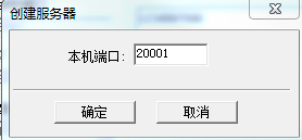
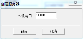
3 | Set module to do tcp client parameters | AT+CIPSTART=1, tcp_client,10.10.10.2,20001\r | OK |
4 | PC from TCP server and automatically connect | Set the local port number: 20001 | Automatically connect with the module's tcp client. +CIPEVENT:1,SERVER,CONNECTED |
5 | AT command mode, the module sends data to the TCP client through the serial port | AT+CIPSEND=1,5\r12345 | TCP client receive area received: 12345 |
6 | AT command mode, TCP client sends data to the module serial port | 1. TCP tool send area sends: 1234567890 | Send successfully |
2. If the module is not automatically received to the serial port, ie: AT+CIPRECVCFG is set to 0, enter the command: AT+CIPRECV=1\r | +CIPRECV:10,1234567890\r\ nOK | ||
3. If the module is automatically received to the serial port, ie: AT+CIPRECVCFG is set to 1, no input command is required. | The module serial port receives: 1234567890 | ||
7 | In transparent mode, the module sends data to the TCP client through the serial port | 1. Module serial input command: AT+CIPSENDRAW\r; | OK |
2. Serial input: abcdefghijklmn | PC-side TCP client received: abcdefghijklmn | ||
8 | Transparent mode, TCP client sends data to module serial port | TCP client send area input data: 1234567890 | Module serial port received: 1234567890 |
The PC uses the TCP/UDP test software to create a TCP server to communicate with the module TCP client. For details, please refer to the following figure.
The TCP/UDP test software workspace is as follows:
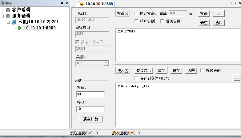
The data transmission and reception work area of the serial port debugging software is as follows: 
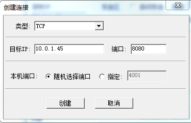
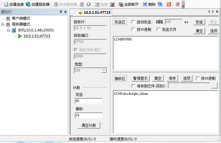
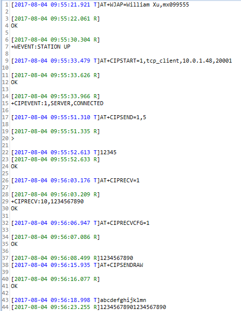
#(2) TCP client in STATION mode
In STATION mode, the module acts as a TCP client, establishes a TCP connection, and communicates. Specific steps are as follows:
Note: Please make sure that the current id connection is disconnected, and then set it. Otherwise, an error will be reported.
Order | Step | Send instruction (or operation) | Return (or phenomenon) |
1 | Set and start STATION mode, wait for the connection to succeed | AT+WJAP=Willam Xu,mx099555\r | OK +WEVNET:STATION UP |
2 | PC connects to Willam Xu and obtains the IP address | PC side Wlan connects to Willam Xu; PC opens cmd.exe and enters the command: ipconfig. | Successfully connected to Willam Xu, PC's IP address: 10.0.1.45 |
3 | Set module to do tcp client parameters | AT+CIPSTART=1, tcp_client, 10.0.1.48, 20001\r | OK |
4 | PC from the TCP server and automatically connect | Set the local port number: 20001 | The connection to the module's tcp client is successful. +CIPEVENT: 1, SEVER, CONNECTED |
5 | AT command mode, the module sends data to the TCP client through the serial port | AT+CIPSEND=1,5\r12345 | TCP client receive area received: 12345 |
6 | AT command mode, TCP client sends data to the module serial port | 1. TCP tool send area sends: 1234567890 | Send successfully |
2. If the module is not automatically received to the serial port, ie: AT+CIPRECVCFG is set to 0, enter the command: AT+CIPRECV=1\r | +CIPRECV:10,1234567890\r\ nOK | ||
3. If the module is automatically received to the serial port, ie: AT+CIPRECVCFG is set to 1, no input command is required. | The module serial port receives: 1234567890 | ||
7 | In transparent mode, the module sends data to the TCP client through the serial port | 1. Module serial input command: AT+CIPSENDRAW\r; | OK |
2. Serial input: abcdefghijklmn | PC-side TCP client received: abcdefghijklmn | ||
8 | Transparent mode, TCP client sends data to module serial port | TCP client send area input data: 1234567890 | Module serial port received: 1234567890 |
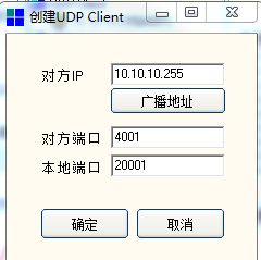
Create a TCP server using TCP/UDP test software to communicate with the TCP client of the module, as shown in the figure below.
PC-side TCP/UDP test software data transceiver work area:

Serial debugging software data transceiver work area:
#3) UDP broadcast
When you need a module to do UDP broadcast (server side) and send UDP broadcast information concurrently, you can refer to the following steps.
#(1) )UDP broadcast in AP mode
In AP mode, the module establishes a UDP broadcast service (server side) and sends UDP broadcast information. Specific steps are as follows:
Order | Step | Send instruction (or operation) | Return (or phenomenon) |
1 | Set and turn on Soft_AP mode | AT+WSAP=jenny,12345678\r | OK |
2 | PC connects to the AP and obtains the IP address | PC side Wlan connects to jenny; PC opens cmd.exe and enters the command: ipconfig. | Successfully connect jenny, PC's IP address: 10.10.10.2 |
3 | Setup Parameters UDP Broadcast Service Parameters | AT+CIPSTART=2,udp_broadcast,10.10.10.255,20001,4001\r | OK Return notification +CIPEVENT:2,UDP,CONNECTED |
4 | PC from UDP client and connect | Set destination Port port number: 4001, local port number: 20001 | Automatic connection to module successfully. |
5 | AT command mode, the module sends data to the UDP server through the serial port | AT+CIPSEND=2,5\12345 | TCP client receiving area received: 12345 |
6 | AT command mode, UDP client sends data to the module serial port | 1. Send area send: 1234567890 | Send successfully |
2. If the module is not automatically received to the serial port, ie: AT+CIPRECVCFG is set to 0, enter the command: AT+CIPRECV=1\r | +CIPRECV:10,1234567890\r\ nOK | ||
3. If the module is automatically received to the serial port, ie: AT+CIPRECVCFG is set to 1, no input command is required. | The module serial port receives: 1234567890 |
|7 |In transparent mode, the module sends data to the UDP server through the serial port|1. Module serial input command: AT+CIPSENDRAW\r;|OK | | | |2. Serial input: abcdefghijklmn|PC-side UDP client received: abcdefghijklmn | |8 | Transparent mode, UDP client sends data to module serial port | UDP client send area input data: 1234567890 | module serial port received: 1234567890 |
Create a UDP broadcast connection on the PC using TCP/UDP test software, and perform UDP communication with the module. For details, please refer to it.
The PC-side UDP connection is created as follows:
PC-side TCP/UDP test software data transceiver work area:
Serial debugging software data transceiver work area
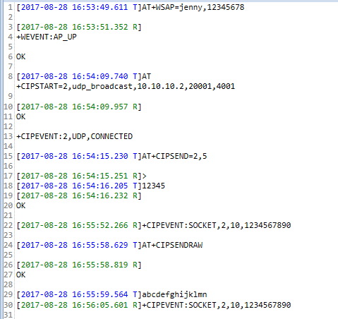
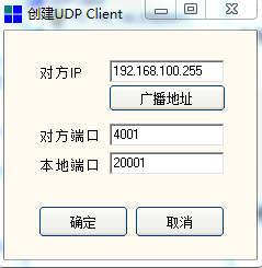
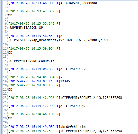
#(2) UDP broadcast in STATION mode
In STATION mode, a UDP server is set up, and the module sends UDP broadcast information. Specific steps are as follows:
Order | Step | Send instruction (or operation) | Return (or phenomenon) |
1 | Set and start STATION mode, wait for the connection to succeed | AT+WJAP=MX,88888880\r | OK +WEVNET:STATION UP |
2 | PC connects to Willam Xu and obtains the IP address | PC side Wlan connects to MX; PC side opens cmd.exe, enter the command: ipconfig. | Successfully connected to Willam Xu, PC's IP address: 192.168.100.118 |
3 | Set the module to do UDP server-side parameters | AT+CIPSTART=2, udp_broadcast, 192.168.100.255, 20001,4001\r | OK |
4 | PC from UDP client and connect | Set destination port Port number: 4001, local port number: 20001 | Successful connection with module udp broadcast. +CIPEVENT: 2, UDP, CONNECTED |
5 | AT command mode, the module sends data to the UDP client through the serial port | AT+CIPSEND=2,5\r12345 | TCP client receive area received: 12345 |
6 | AT command mode, UDP client sends data to the module serial port | 1. TCP tool send area sends: 1234567890 | Send successfully |
2. If the module is not automatically received to the serial port, ie: AT+CIPRECVCFG is set to 0, enter the command: AT+CIPRECV=1\r | +CIPRECV:10,1234567890\r\ nOK | ||
3. If the module is automatically received to the serial port, ie: AT+CIPRECVCFG is set to 1, no input command is required. | The module serial port receives: 1234567890 | ||
7 | In transparent mode, the module sends data to the UDP client through the serial port | 1. Module serial input command: AT+CIPSENDRAW\r; | OK |
2. Serial input: abcdefghijklmn | PC-side UDP client received: abcdefghijklmn | ||
8 | Transparent mode, UDP client sends data to module serial port | UDP client send area input data: 1234567890 | module serial port received: 1234567890 |
Create a UDP broadcast connection on the PC using TCP/UDP test software, and perform UDP communication with the module. For details, please refer to it.
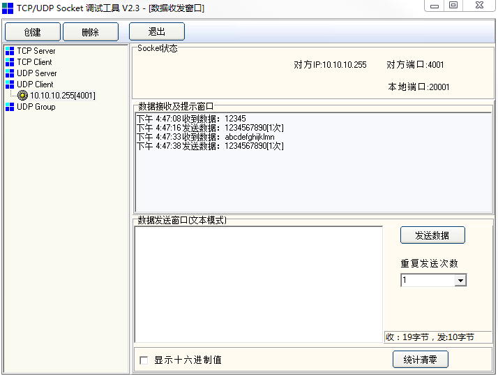
Create a UDP client on the PC side as follows:
PC-side TCP/UDP test software data transceiver work area:
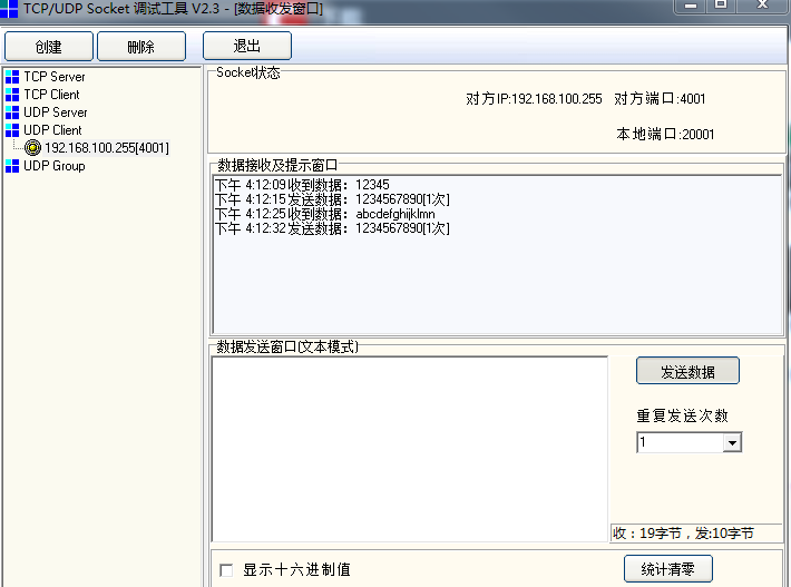
Serial debugging software data transceiver work area:
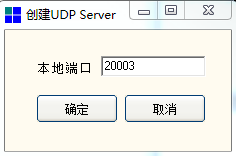
#4) UDP unicast
When you need the module to do UDP unicast (server) and send UDP unicast information concurrently, you can refer to the following steps.
#(1) UDP unicast in AP mode
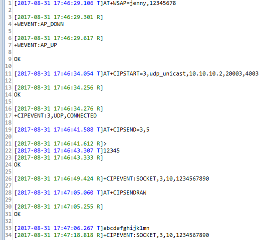
In the WiFi AT command mode, a UDP client is established in the AP mode, and the module sends UDP unicast information. The specific steps are as follows (take the link 1 as an example, the link 2 method is the same):
Order | Step | Send instruction (or operation) | Return (or phenomenon) |
1 | Set and turn on Soft_AP mode | AT+WSAP=jenny,12345678\r | OK |
2 | PC connects to the AP and obtains the IP address | PC side Wlan connects to jenny; PC opens cmd.exe and enters the command: ipconfig. | Successfully connect jenny, PC's IP address: 10.10.10.2 |
3 | Setup Parameters UDP Broadcast Service Parameters | AT+CIPSTART=3,udp_unicast,10.10.10.1,20003,4003\r | OK |
4 | PC from UDP client and connect | Set destination Port port number: 4003, local port number: 20003 | Automatic connection to module successfully. +CIPEVENT:2,UDP,CONNECTED |
5 | AT command mode, the module sends data to the UDP server through the serial port | AT+CIPSEND=2,5\r12345 | TCP client receive area received: 12345 |
6 | AT command mode, UDP client sends data to the module serial port | 1. Send area send: 1234567890 | Send successfully |
2. If the module is not automatically received to the serial port, ie: AT+CIPRECVCFG is set to 0, enter the command: AT+CIPRECV=1\r | +CIPRECV:10,1234567890\r\ nOK | ||
3. If the module is automatically received to the serial port, ie: AT+CIPRECVCFG is set to 1, no input command is required. | The module serial port receives: 1234567890 | ||
7 | In transparent mode, the module sends data to the UDP server through the serial port | 1. Module serial input command: AT+CIPSENDRAW\r; | OK |
2. Serial input: abcdefghijklmn | PC-side UDP client received: abcdefghijklmn | ||
8 | Transparent mode, UDP client sends data to module serial port | UDP client send area input data: 1234567890 | module serial port received: 1234567890 |
Create a UDP unicast connection on the PC as follows:
PC-side TCP/UDP test software data transceiver work area:

Serial debugging software data transceiver work area:
#(2) UDP unicast in STATION mode
In the WiFi AT command mode, a UDP client is established in the STATION mode, and the module sends UDP unicast information. The specific steps are as follows (take the link 1 as an example, the link 2 method is the same):
Order | Step | Send instruction (or operation) | Return (or phenomenon) |
1 | Set and start STATION mode, wait for the connection to succeed | AT+WJAP=MX,88888880\r | OK +WEVNET:STATION UP |
2 | PC connects to Willam Xu and obtains the IP address | PC side Wlan connects to MX; PC side opens cmd.exe, enter the command: ipconfig. | Successfully connected to Willam Xu, PC's IP address: 192.168.100.105 |
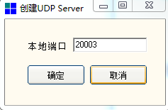
3 | Set the module to do UDP server-side parameters | AT+CIPSTART=3,udp_unicast,192.168.100.105,20003,4003\r | OK |
4 | PC from UDP client and connect | Set destination port Port number: 4003, local port number: 20003 | Automatic connection with the module's udp client. +CIPEVENT: 3, UDP, CONNECTED |
5 | AT command mode, the module sends data to the UDP client through the serial port | AT+CIPSEND=3,5, within 3 seconds, the input string: 12345 | TCP client receiving area received: 12345 |
6 | AT command mode, UDP client sends data to the module serial port | 1. TCP tool send area sends: 1234567890 | Send successfully |
2. If the module is not automatically received to the serial port, ie: AT+CIPRECVCFG is set to 0, enter the command: AT+CIPRECV=1\r | +CIPRECV:10,1234567890\r\ nOK | ||
3. If the module is automatically received to the serial port, ie: AT+CIPRECVCFG is set to 1, no input command is required. | The module serial port receives: 1234567890 | ||
7 | In transparent mode, the module sends data to the UDP client through the serial port | 1. Module serial input command: AT+CIPSENDRAW\r; | OK |
2. Serial input: abcdefghijklmn | PC-side UDP client received: abcdefghijklmn | ||
8 | Transparent mode, UDP client sends data to module serial port | UDP client send area input data: 1234567890 | module serial port received: 1234567890 |
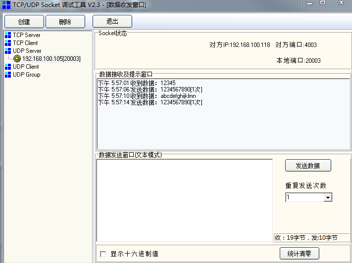
Create a UDP unicast connection on the PC as follows:
PC-side TCP/UDP test software data transceiver work area:
Serial debugging software data transceiver work area:

#6.Easylink Distribution Network
When you need to use Easylink distribution network to distribute the module to the network, you can send an AT command to the module to start the distribution network. Specific examples are as follows:
Order | Step | Send instruction (or operation) | Return (or phenomenon) |
1 | Regardless of the operating mode of the module | AT+SMARTSTART=1\r | +WEVENT:STATION_DOWN, STATION disconnected |
2 | Mobile phone open Easylink distribution network APP, enter ssid and key, start distribution network | ---- | +WEVENT:STATION_UP, distribution network success |
#7.Airkiss Distribution Network
When the Airkiss of the WeChat public account is required to be used as a module distribution network, an AT command can be sent to the module to start the distribution network. details as follows:
Order | Step | Send instruction (or operation) | Return (or phenomenon) |
1 | Only when the configuration command is sent, the Airkiss distribution network can discover the device | AT+SMARTCFG=gh_420af5d2de71_9b6ee2f805e286e2, gh_420af5d2de71\r (Note: The first parameter is the original ID of your WeChat public number: original_id The second parameter is the device ID generated after the product is created under the public number: device_id) | OK |
2 | Start Airkiss Distribution Status | AT+SMARTSTART=2\r | +WEVENT:STATION_DOWN,STATION Disconnected |
3 | Mobile phone to open your WeChat public account or scan the QR code below, enter the Airkiss matching page, enter ssid and key, start distribution network | ---- | +WEVENT:STATION_UP, distribution network success, And APP side list discovery device: Mi Ke deer |
Airkiss distribution network test QR code:

#8.Get SNTP time
When the module is required to obtain the network synchronization time, an AT command can be sent to the module to obtain the SNTP time.
Tip: To obtain network time, the module must be connected to a router, or enable STATION mode, or Easylink distribution network is successful, or Airkiss distribution network is successful, that is, in STATION_UP state.
Specific steps are as follows:
Order | Step | Send instruction (or operation) | Return (or phenomenon) |
1 | Module Connection Router | Start STATION Work Mode or Distribution Network | +WEVENT=STATION_UP |
2 | Configure SNTP time zone and server domain name | AT+SNTPCFG=+8,cn.ntp.org.cn,pool.ntp.org\r | OK |
3 | Get SNTP Time | AT+SNTPTIME\r | +SNTPTIME:2017-09-05T14:33:05.022320 \r\n OK |
#9.Get RTC time
When the module is required to obtain the RTC time of the module, an AT command can be sent to the module to obtain the RTC time.
Specific steps are as follows:
Order | Step | Send instruction (or operation) | Return (or phenomenon) |
1 | When the SNTP time synchronization is not done, the RTC time obtained is: the system running time from 0:0:0 on January 1, 1970 | AT+RTCGET\r | +RTCGET:1970 -01-01T00:01:00.028856 \r\n OK |
2 | After SNTP time synchronization, the obtained RTC time is: the standard time of the current specified time zone. | AT+RTCGET\r | such as: +RTCGET:2017-09-05T14:33:05.022320\r\n OK |
3 | When the system is powered off, the RTC time is not saved and will be restored to the initial time: 0:00:00 on January 1, 1970, and will not restart from the initial test time until power is restored again. RTCGET\r` | +RTCGET:1970-01-01T00:01:00.090555 \r\n OK |
#10.MQTT protocol communication use case
#1) Implementing mqtt communication with Qingke Fog Cloud
The following explains how to implement MQTT communication between the device and the Fog cloud server through AT commands, including: MQTT connection establishment, subscription topic, and publishing data.
Note: Fog Cloud Server does not require a certificate of authentication and requires SSL encryption.
Order | Step | Send command (or operation) |
1 | Connection Router | AT+WJAP=ssid,password\r |
Back | OK , +WEVNET:STATION UP | |
2 | Enable event push function | AT+MQTTEVENT=ON\r |
Back | OK | |
3 | Setting the MQTT username and password | AT+MQTTAUTH=6618fdda2a4f11e7a554fa163e876164/77a0853e3a1a11e7a554fa163e876164, ibV/zzpOyHKDUVH4EEXK7RoZtJHp6GTj6fazxst2+k4=\r |
Back | OK | |
4 | Set host and port number | AT+MQTTSOCK=6618fdda2a4f11e7a554fa163e876164.mqtt.iot.gz.baidubce.com,1884\r |
Back | OK | |
5 | Close MQTT certificate verification | AT+MQTTCAVERIFY=OFF,OFF\r |
Back | OK | |
7 | Enable SSL Encryption | AT+MQTTSSL=ON\r |
Back | OK | |
8 | Set Client Identifier | AT+MQTTCID=77a0853e3a1a11e7a554fa163e876164\r\r |
Back | OK | |
9 | Set MQTT Heartbeat Cycle | AT+MQTTKEEPALIVE=30\r |
Back | OK | |
10 | Enable MQTT automatic reconnection function | AT+MQTTRECONN=ON\r |
Back | OK | |
11 | Enable MQTT power-on automatic connection function | AT+MQTTAUTOSTART=ON\r |
Back | OK | |
12 | Start MQTT Service | AT+MQTTSTART\r |
Back | OK and +MQTTEVENT:CONNECT,SUCCESS | |
13 | Subscription theme | AT+MQTTSUB=0,6618fdda2a4f11e7a554fa163e876164/df358c1a348611e7a554fa163e876164/77a0853e3a1a11e7a554fa163e876164/status/json,0\r |
Back | +MQTTEVENT:0,SUBSCRIBE,SUCCESS | |
14 | Publish Settings | AAT+MQTTPUB=6618fdda2a4f11e7a554fa163e876164/df358c1a348611e7a554fa163e876164/77a0853e3a1a11e7a554fa163e876164/status/json,0\r |
Back | OK | |
15 | Publish data | AT+MQTTSEND=6\r, after returning >, enter the data: 123456 |
Return | +MQTTEVENT:PUBLISH,SUCCESS, Receive the same data returned by the same subject at the same time: +MQTTRECV:0,6,123456 | |
16 | Unsubscribe topic | AT+MQTTUNSUB=0\r |
Return | OK and +MQTTEVENT:0, UNSUBSCRIBE, SUCCESS | |
17 | Close MQTT Service | AT+MQTTCLOSE\r |
Back | OK and +MQTTEVENT:CLOSE,SUCCESS |
#2) Implementing mqtt communication with Amazon aws cloud
The following explains how to implement MQTT communication between a device and an AWS cloud server through the MQTT communication AT command. The server requires certificate verification, so there are three more certificate verification instructions than Fog communication. The specific process is as follows, including: MQTT connection establishment, subscription topic, and release data.
Description:
- Since Amazon provides paid services, it only provides a complete usage process and does not provide real usernames, passwords and certificates.
- Users need to register the service on Amazon to obtain the relevant user name, password and certificate according to the specific product or project. [Click here to enter the Amazon aws official website] (https://aws.amazon.com (opens new window)).
- When the user actually delivers the certificate, he must append Ctrl+Z (ASCII code is 0x1A, which is not part of the certificate) at the end of the certificate. As the end of the certificate delivery, the module will store the certificate in flash.
Order | Step | Send instruction (or operation) | Return (or phenomenon) |
1 | Connection Router | AT+WJAP=ssid,password\r | OK and +WEVNET:STATION UP |
2 | Enable event push function | AT+MQTTEVENT=ON\r | OK |
3 | Set MQTT username and password | AT+MQTTAUTH=UserName,PassWord\r | OK |
4 | Set Host and Port Number | AT+MQTTSOCK=a1lqshc4oegz64.iot.us-west-2.amazonaws.com,8883\r | OK |
5 | Enable MQTT certificate verification | AT+MQTTCAVERIFY=ON,ON\r | OK |
6 | Pass the server root certificate | AT+SSLCERTSET=0\r | OK |
7 | Send server root certificate file content | Server root certificate file content | OK |
8 | Pass client certificate | AT+SSLCERTSET=1\r | OK |
9 | Send client certificate file content | Client certificate file content | OK |
10 | Pass client private key | AT+SSLCERTSET=2\r | OK |
11 | Send client private key file content | client private key file content | OK |
12 | Enable SSL Encryption | AT+MQTTSSL=ON\r | OK |
13 | Set Client Identifier | AT+MQTTCID=MiCO\r | OK |
14 | Set MQTT Heartbeat Cycle | AT+MQTTKEEPALIVE=10\r | OK |
15 | Turn off MQTT automatic reconnection function | AT+MQTTRECONN=OFF\r | OK |
16 | Enable MQTT power-on automatic connection function | AT+MQTTAUTOSTART=ON\r | OK |
17 | Start MQTT Service | AT+MQTTSTART\r | OK and +MQTTEVENT:CONNECT,SUCCESS |
18 | Subscription theme 0 | AT+MQTTSUB=0,$aws/things/myLight/shadow/delete/accepted,1\r | OK and +MQTTEVENT:0,SUBSCRIBE,SUCCESS |
19 | Subscription theme 1 | AT+MQTTSUB=1, $aws/things/myLight/shadow/update/delta,0\r | OK and +MQTTEVENT:1,SUBSCRIBE,SUCCESS |
20 | Subscription theme 2 | AT+MQTTSUB=2,$aws/things/myLight/shadow/update,0\r | OK and +MQTTEVENT:2,SUBSCRIBE,SUCCESS |
21 | Publish Settings | AT+MQTTPUB=$aws/things/myLight/shadow/update,0\r | OK |
22 | Publish data | AT+MQTTSEND=6\r, after returning >, enter the data: 123456 | +MQTTEVENT:PUBLISH,SUCCESS, and receive the data returned by the same subject of the subscription:+MQTTRECV:2,6,123456 |
23 | Unsubscribe topic 1 | AT+MQTTUNSUB=1\r | OK and +MQTTEVENT:1, UNSUBSCRIBE, SUCCESS |
24 | Close MQTT Service | AT+MQTTCLOSE\r | OK and +MQTTEVENT:CLOSE,SUCCESS |
← AT Command Detail FAQ →