
# Bootloader Mode
#What's Bootloader?
Bootloader is a small program that runs before the operating system kernel or user application runs. Through this small program, we can initialize the hardware device and create a map of the memory space to bring the system's hardware and software environment to a suitable state to prepare the correct environment for the final call to the operating system kernel or user application.
This document contains a list of commands for the MXOS Bootloader mode, the steps to go and the specific command usage.
#Function list
MXOS's Bootloader mode provides users with the following commands:
Code | Name | Function |
0 | BOOTUPDATA | Update bootloader firmware |
1 | FWUPDATA | Update application application firmware |
2 | DRIVERUPDATE | Update RF RF drive |
3 | PARAUPDATE | Update MXOS setup parameters |
4 | FLASHUPDATE | Update flash content |
5 | MEMORYMAP | List flash memory allocation map |
6 | BOOT | Running the application |
7 | REBOOT | Restart |
#Enter step
- Take the MXKit development board as an example, connect the “Debug Serial Port” (ie USB power socket) to the PC via “Micro-USB cable”.
- Connect the development board "User Serial Port (UART in Aduino Interface)" to the PC via the "USB to TTL Level Module" board.
- Open the SecureCRT serial port debugging tool software and find the COM port number corresponding to the “user serial port” in the device manager of the PC.
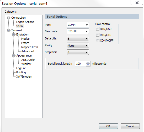
- Create a “user serial port” quick connection in SecureCRT. For the serial port parameter configuration, please refer to: Type: Serial, “user serial port” COM port, baud rate: 921600, data bit: 8bit, parity: none, stop bit :1.
The parameters are as follows:
- For the MXKit development board of BOOT and STATUS pin switch, set the DIP switch status of the development board, BOOT: ON (low level), STATUS: OFF (high level), then press "Reset" Press the button to reset the development board.
- For the MXKit development board with the BOOT and STATUS pins connected to the push button switch, press and hold the BOOT button, then press RESET to enter the bootloader mode.
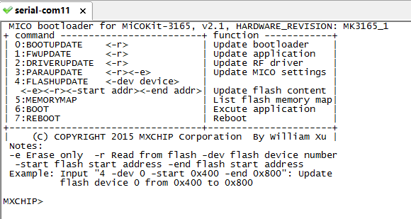
- The Bootloader log information output by SecureCRT is as follows:
#Cmmand usage example
#Command 0: Update or read the bootloader firmware
- Update Bootloader firmware
- Refer to Bootloader mode to enter the step and enter Bootloader mode.
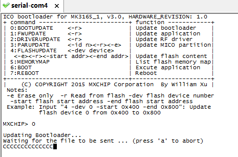
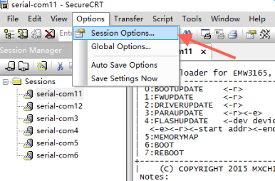
- Before entering the command, you need to change the setting: Session Options → Connection → Serial → Flow Control to cancel the previously selected RTS/CTS; then enter: 0, press Enter, as shown below;
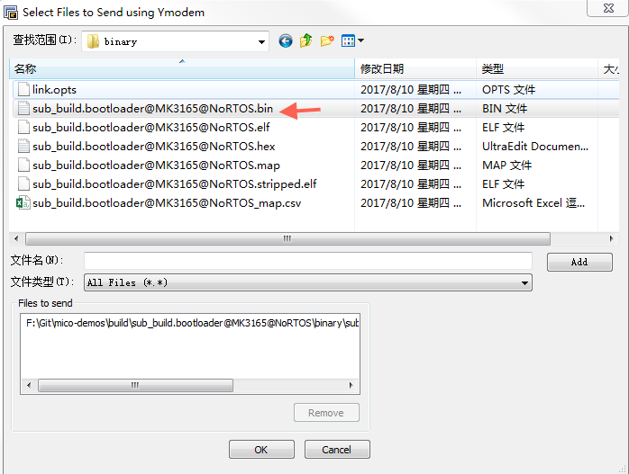
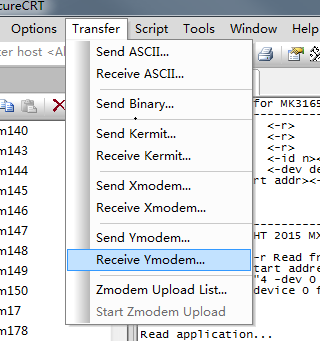
- Select Transfer → Send Ymodem in SecureCRT → select the updated Bootloader firmware;
- After confirmation, the firmware burning interface is displayed as shown in the figure.
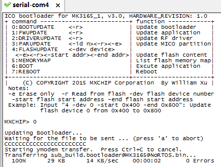
At this moment, the bootloader firmware update is complete.
#2. Read the bootloader firmware
- Refer to Bootloader mode to enter the step and enter Bootloader mode.
- Before entering the command, you need to change the setting Session Options → Connection → Serial → Flow Control to cancel the previously selected RTS/CTS; then enter: 0 -r, enter;
- Select Transfer→Receive Ymodem in SecureCRT

- After confirmation, the figure is displayed.
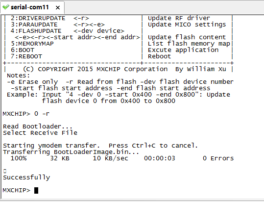
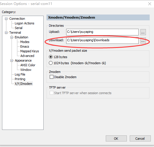
At this moment, the Bootloader firmware is read, and the read file is saved in the following directory, as shown in the figure:


#Command 1: Update or read application firmware
Update or read the method, same as the command 0: Bootloader operation method.
#Update the application firmware
- Refer to Bootloader mode to enter the step and enter the bootloader mode.
- Before entering the command, you need to change the setting: Session Options → Connection → Serial → Flow Control to cancel the previously selected RTS/CTS; then enter: 1, enter, as shown below
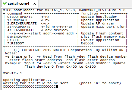
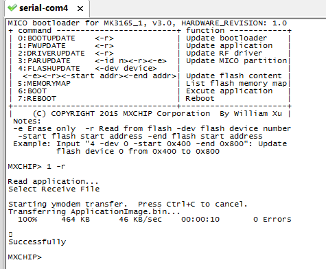
- In the SecureCRT, select Transfer→Send Ymodem→Select the updated application firmware and click OK.
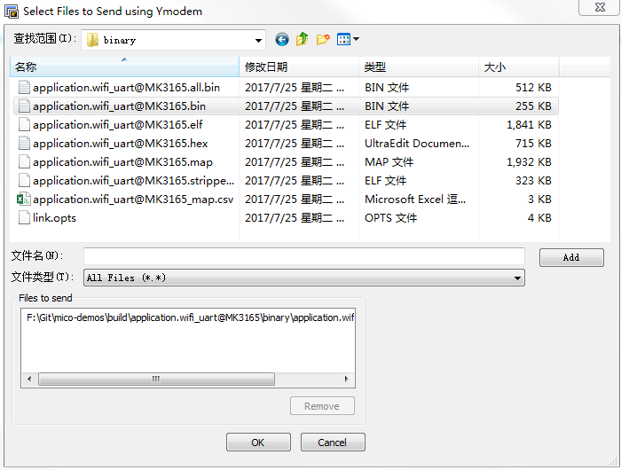
- After confirmation, the firmware burning interface is displayed as shown in the figure.

At this moment the application firmware update is complete.
#2. Read application firmware
- Refer to Bootloader mode to enter the step and enter Bootloader mode.
- Before entering the command, you need to change the setting Session Options → Connection → Serial → Flow Control to cancel the previously selected RTS/CTS; then enter: 1 -r, enter;
- Select Transfer→Receive Ymodem in SecureCRT

- After confirmation, the figure is displayed.
At this, the application firmware is read, and the read file is saved in the following directory, as shown in the figure:
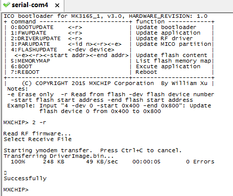
#Command 2: Update or read the RF RF driver firmware
Update or read the method, same as the command 0: Bootloader operation method.
#1. Update RF RF Driver Firmware
- Refer to Bootloader mode to enter the step and enter the bootloader mode.
- Before entering the command, you need to change the setting: Session Options → Connection → Serial → Flow Control to cancel the previously selected RTS/CTS; then enter: 2, enter, as shown below;

- In the SecureCRT, select Transfer→Send Ymodem→Select the updated application firmware and click OK.

- After confirmation, the firmware burning interface is displayed as shown in the figure.
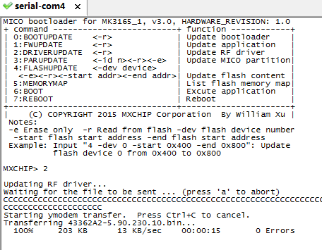
At this point, the application firmware update is complete.
#2. Read the RF RF driver firmware
- Refer to Bootloader mode to enter the step and enter Bootloader mode.
- Before entering the command, you need to change the setting Session Options → Connection → Serial → Flow Control to cancel the previously selected RTS/CTS; then enter: 2 -r, enter;
- Select Transfer→Receive Ymodem in SecureCRT
- After confirmation, the figure is displayed.
At this point, the application firmware is read, and the read file is saved in the following directory, as shown in the figure:


#Command 3: Update or read or erase MXOS setup parameters
#Update MXOS setting parameters
- Refer to the Bootloader mode to enter the step and enter the Bootloader mode.
- Before entering the command, you need to change the setting Session Options → Connection → Serial → Flow Control to cancel the previously selected RTS/CTS; then enter: 3 Enter;
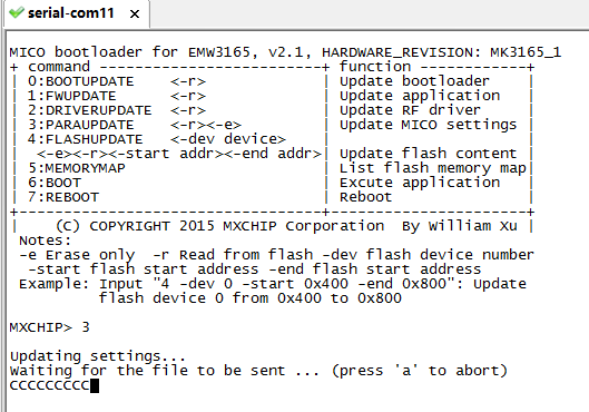
- Select Transfer→Send Ymodem in SecureCRT and select the bin file to be updated to start the update.
#Read MXOS setting parameters
- Refer to the Bootloader mode to enter the step and enter the Bootloader mode.
- Before entering the command, you need to change the setting Session Options → Connection → Serial → Flow Control to cancel the previously selected RTS/CTS; then enter: 3 -r, enter;
- After selecting Transfer→Receive Ymodem in SecureCRT, the display is as shown.
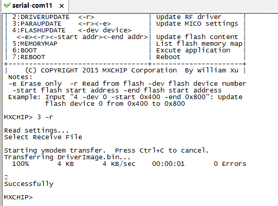
At this point, the MXOS setup parameters are read and the read files are stored in the specified directory of SecureCRT.
#Erase MXOS setting parameters
- Refer to the Bootloader mode to enter the step and enter the Bootloader mode.
- Before entering the command, you need to change the setting Session Options → Connection → Serial → Flow Control to cancel the previously selected RTS/CTS; then enter: 3 -e, enter; display as shown.

#Command 4: Read or erase/update Flash content
#1. Read the contents of the specified Flash area
- Refer to the Bootloader mode to enter the step and enter the Bootloader mode.
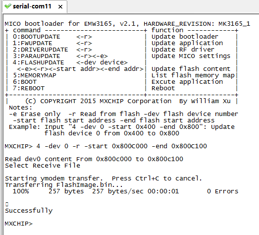
- Before entering the command, you need to change the setting Session Options → Connection → Serial → Flow Control to cancel the previously selected RTS/CTS; then enter: 4 –dev 0 -r –start 0x800C000 –end 0x800C100, press Enter;
- Select Transfer→Receive Ymodem in SecureCRT, and the read file will be stored in the specified directory of SecureCRT.
#2. Erase the specified Flash area content
- Refer to the Bootloader mode to enter the step and enter the Bootloader mode.
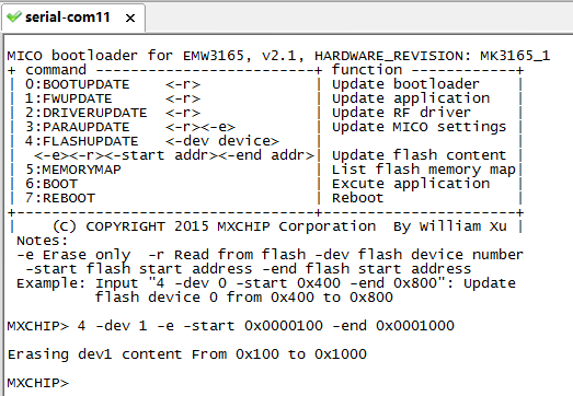
- Before entering the command, you need to change the setting Session Options → Connection → Serial → Flow Control to cancel the original selected RTS/CTS; then enter: 4 –dev 0 –e –start 0x0000100 –end 0x0001000, enter; log As shown.
#3. Update the specified Flash area content
- Refer to the Bootloader mode to enter the step and enter the Bootloader mode.
- Before entering the command, you need to change the setting Session Options → Connection → Serial → Flow Control to cancel the previously selected RTS/CTS; then enter: 4 –dev 0 –start 0x800C000 –end 0x800C100, press Enter.
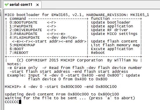
Select Transfer→Send Ymodem in SecureCRT, select the .bin file to be burned, and then confirm it, you can successfully burn it.
#Command 5: Query the list of flash memory address allocations
- Refer to the Bootloader mode to enter the step and enter the Bootloader mode.
- Before entering the command, you need to change the setting Session Options → Connection → Serial → Flow Control to cancel the previously selected RTS/CTS; then enter: 5, enter; display as shown. (Note: 0x08000000 in the parameter is the starting address, 0x00004000 is the length of the flash area)

- At this point, the flash memory allocation list is queried.
#Command 6: Run the application
- Refer to the Bootloader mode to enter the step and enter the Bootloader mode.
- Before entering the command, you need to change the setting Session Options → Connection → Serial → Flow Control to cancel the previously selected RTS/CTS; then enter: 6, enter; display as shown.
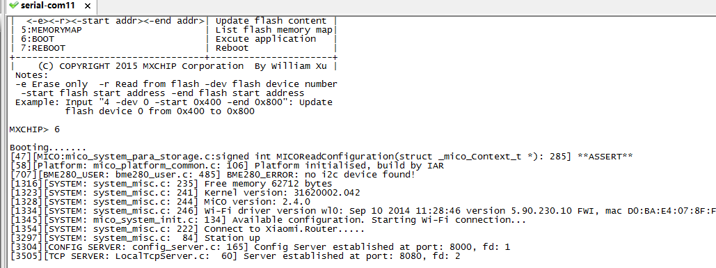
At this point, the flash memory allocation list is queried.
#Command 7: Restart the module
- Refer to the Bootloader mode to enter the step and enter the Bootloader mode.
- Before entering the command, you need to change the setting Session Options → Connection → Serial → Flow Control to cancel the previously selected RTS/CTS; then enter: 7, enter; display as shown.
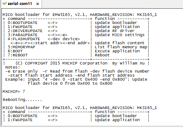
END.