
# xAT Introduction
xAT Firmware is developed by MXCHIP, and the software command system runs on MX1510 series BLE modules.
Using the AT firmware and AT Commands, users can easily and quickly add BLE communication functions for embedded devices. It greatly shortens the development cycle and achieves rapid listing.
#xAT Command Type
Type | Discription | |
TEST | AT+<Command Name>=? | Query the internal parameters of the setting command and their value ranges. |
QUERY | AT+<Command Name>? | Return the current parameter value. |
SET | AT+<Command Name>=<…> | Set user-defined parameter values and run the command. |
EXECUTE | AT+<Command Name> | Run commands without user-defined parameters. |
- Not every AT command has the above four types of commands.
- Input parameters in the command. Currently, only string parameters and integer numeric parameters are supported.
- The parameters in angle brackets<>cannot be omitted.
- Parameters in square brackets [] can be omitted, and default values are used when omitted. In the setting command, if parameters are omitted, these omitted parameters will not be set, and the previous values or default values will be maintained, for example:
AT+BLEADVDATAEX="12345678",1,
AT+BLEADVDATAEX="12345678",1,"FFF0"
- When there are still parameters to be filled after the omitted parameters, they must be separated by commas, for example:
AT+BLEADVDATAEX="12345678",,"FFF0"
- Use double quotes to indicate string parameters, for example:
AT+BLENAME="XBT peripheral"
- Special characters need to be escaped, such as, ", , etc.
\\:Escape the backslash.\,:Escape commas. Commas separating parameters do not need to be escaped.":Escape double quotes. Double quotes representing string parameters do not need to be escaped.\<any>:Escape<any>characters, that is, only<any>characters are used, no backslash is used.
- Only the special characters in the AT command need to be escaped. For example, when the AT command port prints>waits for input data, the data does not need to be escaped.
AT+BLENAME=""XBT" peripheral"
- The default baud rate for AT commands is 115200.
- The length of each AT command should not exceed 255 bytes (including
(CR-LF)). - The AT command ends with a new line (CR-LF), so the serial port tool should be set to "new line mode".
- Use AT+SYSLOG to open the error code display function. The format of AT command error code:
((AT_MODULE_NUM<<24) | ((subcategory)<<16) | ((extension)&0xFFFF)), where AT_ MODULE_ NUM=1. The subcategory is as follows. For more information, refer to at in the AT project source code_ Errno. h file.
enum {
    AT_SUB_OK                       = 0x00,              /*!< OK */
    AT_SUB_COMMON_ERROR             = 0x01,              /*!< reserved */
    AT_SUB_NO_TERMINATOR            = 0x02,              /*!< terminator character not found ("\r\n" expected) */
    AT_SUB_NO_AT                    = 0x03,              /*!< Starting "AT" not found (or at, At or aT entered) */
    AT_SUB_PARA_LENGTH_MISMATCH     = 0x04,              /*!< parameter length mismatch */
    AT_SUB_PARA_TYPE_MISMATCH       = 0x05,              /*!< parameter type mismatch */
    AT_SUB_PARA_NUM_MISMATCH        = 0x06,              /*!< parameter number mismatch */
    AT_SUB_PARA_INVALID             = 0x07,              /*!< the parameter is invalid */
    AT_SUB_PARA_PARSE_FAIL          = 0x08,              /*!< parse parameter fail */
    AT_SUB_UNSUPPORT_CMD            = 0x09,              /*!< the command is not supported */
    AT_SUB_CMD_EXEC_FAIL            = 0x0A,              /*!< the command execution failed */
    AT_SUB_CMD_PROCESSING           = 0x0B,              /*!< processing of previous command is in progress */
    AT_SUB_CMD_OP_ERROR             = 0x0C,              /*!< the command operation type is error */
}; - The command header (AT+command name) of AT command is not case sensitive. The string parameter in the parameter is case sensitive, but if a string is used to represent a hexadecimal number, it is case insensitive.
14. After the device is started, it will actively send an OK\r\n
#xAT command with parameters saved in Flash
The parameter changes of the following AT commands will always be saved in the KV area of flash, so they will be used directly after restart.
AT+UART_ DEF: AT+UART_ DEF=115200,8,1,0,3
Whether the parameter changes of other commands are saved to flash can be configured through the AT+SYSSTORE command. By default, they are saved in the KV area. Please refer to the command description for details.
Some configuration parameters are directly included in binary files in the form of JSON configuration files, which can ensure that modules can be used without configuration after burning. Please refer to: Modify the default settings in this page.
#XAT return message type
There are two types of xAT messages returned from the xAT command port: xAT response (passive) and xAT message report (active).
#Passive response
Each input xAT command will return a response, telling the sender the execution result of the xAT command. The last message of the response must be OK or ERROR.
AT Response | Discription |
OK | After the command processing, return to OK |
ERROR | AT command error or error during execution |
+<Command Name>:... | Describe the AT command processing results in detail |
#Active response
Through xAT message reporting, xAT will report important status changes or messages in the system. Most active messages can be masked using AT+SYSMSG and AT+CIPMODE commands.
xAT Message report | Description |
OK | After the system is started, it will be sent automatically only once |
> | XAT is waiting for the user to enter data |
+BLECONN | Bluetooth LE is connected |
+BLEDISCONN | Bluetooth LE is disconnected |
+SEND_OK | In AT command mode, the serial port data has been received and sent to the protocol stack, but it does not mean that the data has been sent to the opposite end. |
+SEND_FAIL | In AT command mode, the serial port data has been received and sent to the protocol stack, but it does not mean that the data has been sent to the opposite end. |
+SEND_CANCELED | In AT command mode, an error occurs when sending data to the protocol stack |
+NOTIFY_ENABLED | The client has enabled listening to the server to send transparent notify messages |
+NOTIFY_DISABLED | The client has stopped listening to the server for sending transparent notify messages |
+WRITE,<xxx> | Write <xxx>through Bluetooth LE |
#Operating mode switching
After the module is started, it starts broadcasting immediately, waiting for the connection of the BLE Central device, and the serial port driver directly enters the preset working mode.
The default value can be set in config It can be modified in json and burned to the configuration partition in Flash. For details, refer to Modify Default Settings in this page.
At the same time, in AT mode, you can use the command to switch the working mode.
The contents of the default broadcast package after the module is started are as follows, which can be flexibly modified and controlled using AT commands.
Type:0x01(BT_DATA_FLAGS);Data:BT_LE_AD_GENERAL | BT_LE_AD_NO_BREDR
According to the UUID type that transparent service used, choose corresponding type:
- Type:0x03(BT_DATA_UUID16_ALL),Data:UUID of transparent service.
- Type:0x05(BT_DATA_UUID32_ALL),Data:UUID of transparent service.
- Type:0x07(BT_DATA_UUID128_ALL),Data:UUID of transparent service.
Type:0xFF(BT_DATA_MANUFACTURER_DATA);Data:[0x22, 0x09, 0x00, XX, XX],XX XX is the minimum 2 bytes of the module MAC address.
Type:0x09(BT_DATA_NAME_COMPLETE);Data is the name of GAP.
The UUID of the Transparent service, Data In feature and Data Out feature can be modified in the configuration file. The default values are 0xFE00, 0xFE01 and 0xFF02, respectively.
The serial port can process data in the following modes:
#RAW DATA Mode
Raw data mode is also known as transparent transmission mode, that is, the serial port data is sent to the network protocol stack without modification.
● The module receives data from the serial port: the serial port receives data, composes the received data into a data frame, and sends the data frame to the Data Out feature of BLE's Transparent service.
If
- The connection between the device and the Central device is established
- If the CCCD Notification flag of the Data Out feature is turned on, the data can be sent to the Central device. The data received by the serial port forms a data frame according to the following two conditions, and the parameters can be adjusted in the configuration file:
- Length packaging: The received data reaches the set maximum length. The default is 256 bytes.
- Timeout packaging: After receiving a data, if no new data is received within a certain period of time, the received data will be packaged. The default value is 50 milliseconds.
● The module sends data to the serial port: the following data will be sent to the serial port
- The same Central device can write data to the Data In feature of the Transparent service, and the load of the received network data frame is also directly sent to the serial port.
- When an event is generated, the event message will be output on the serial port. This function uses the msg in the configuration file_ Flag. These events can be found in the "Active Response" section of the BLE AT command set.
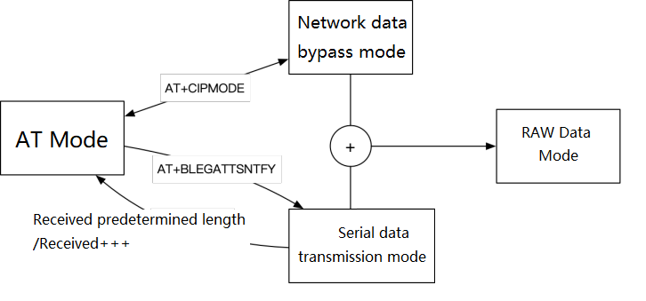
#AT Mode
Parse data in the format of AT command (starting with AT and ending with CR-LF) and send it to AT subsystem for processing. In this mode, the echo function of AT command is automatically started, and the input of serial port will not be timeout processed, so that the user can manually input AT command on the terminal.
In AT mode, the system can modify the processing mode of serial port data through AT commands:
● To process the data received by the module from the network, use the AT+CIPMODE command:
○ When CIPMODE=0 (default), the received network data is output to the serial port through the AT event format, namely:+WRITE,<xxx>:<raw data>
○ When CIPMODE=1, the received network data is directly transmitted to the serial port, which is consistent with the processing mode in RAW Data mode. This mode can become the network data bypass mode.
● The AT+BLEGATTSNTFY command is used to process the data obtained by the module from the serial port. After the serial port outputs>characters, temporarily enter the serial port data transmission mode. The data received by the serial port is directly sent to the network. When receiving data of a specific length or three consecutive+characters, the mode will automatically exit.
The following is the state switch diagram:
#AUTO Mode(Default)
AUTO mode combines RAW DATA mode and AT mode. The serial port data is processed as follows:
- Processing method for module to obtain data from serial port: automatically detect whether it conforms to AT instruction format: start with AT in a data package, and if CRLF is detected, extract the data from AT to CRLF, and process it according to AT mode, otherwise process it in Raw Data mode. At the same time, due to the need to switch between RAW DATA mode and AT mode, there are some differences between AT instruction processing under single AT mode and RAW DATA mode:
- AT command has no echo function
- When detecting data packets, there is the same timeout packaging mechanism as in Raw Data mode. Therefore, when entering the AT command, the input interval of each byte must be less than the interval time (50 milliseconds by default). When using the serial port terminal again, it is not allowed to input a single character one by one, but should input a complete AT instruction to the serial port at one time.
- When entering AT command, ensure that AT is at the head. That is, after sending Raw data, you should wait at least 50 milliseconds.
● Processing of data received by the module from the network, and directly transmitting the received network data to the serial port. The serial port also outputs the event information of AT system, and can be configured through AT+SYSMSG.
#Modify Default Configuration
The xAT system can be used after power on. If you need to modify the system default parameters, you can use the configuration file to modify them, and package the configuration file and firmware together to form a new firmware that is burned to the module. Instead, the AT command can be used to dynamically set the working parameters of the module or perform specific functions when the module is working.
The configuration file format is a JSON format text, which is released along with the firmware: xAT firmware release.
For the method of synthesizing firmware and configuration files, refer to HyperPack Tool Usage.
Configurable items and descriptions are as follows:
{
  "module": "MX1510",                 // Module model, or directly use chip model MX1510.
                                      // By setting the module model, the pin number in the configuration file is mapped to the selected module.
                                      // Refer to the corresponding data manual for module pin functions. If the module model used is uncertain, the chip model can be used directly.
  "device_name": "XAT",               // Default name. The last two bytes of MAC address will be added as suffix in the broadcast package.
  "conf_version": "001",              // The version number of the configuration file should not be modified.
  "uart": {
    "pack_mode": 2,                 // UART data packaging processing mode: 0: transparent transmission, 1: AT command, 2: automatic.
    "raw_packet_max_length": 256,   // The maximum length of transparent data packet shall not exceed 256 bytes.
    "raw_packet_gap_time": 50,      // Time interval of transparent data packet, in ms. That is, after receiving a byte, if no additional data is received within the set time, the previous data will be packed and processed.
    "msg_flag": 5,                  // BIT0: Exit the transparent receiving mode, print "+QUIT".
                                    // BIT1: Print detailed event information.
                                    // BIT2: Print event information.
    "uart": 1,                      // UART port number.
    "tx_pin": 20,                   // tx Pin number, refer to the selected module or chip in "module".
    "rx_pin": 19,                   // rx Pin number, refer to the selected module or chip in "module".
    "cts_pin": -1,                  // cts Pin number, refer to the selected module or chip in "module".
    "rts_pin": -1,                  // rts Pin number, refer to the selected module or chip in "module".
    "baud_rate": 115200,            // Serial port data baud rate.
    "data_width": 3,                // 0: 5bits, 1: 6bits, 2: 7bits, 3: 8bits, 4: 9bits.
    "parity":0,                     // 0: No check, 1: even check, 2: odd check.
    "stop_bits": 0,                 //0: 1 stop bit, 1:2 stop bit.
    "flow_control": 0               // 0: No flow control, 1: CTS, 2:RTS, 3:CTSRTS.
  },
  "transparent": {                  // GATT Transparent service configuration.
    "service_uuid": "FE00",         // Transparent service UUID,such as: "1234", "12345678", "6E400001-B5A3-F393-E0A9-E50E24DCCA9E".
    "data_out_uuid": "FE01",        // Transparent data transmission attribute(notify)UUID,such as: "1234", "12345678", "6E400001-B5A3-F393-E0A9-E50E24DCCA9E".
    "data_in_uuid": "FE02"          // Transparent data receiving attribute(write without response)UUID,such as: "1234", "12345678", "6E400001-B5A3-F393-E0A9-E50E24DCCA9E".
  }
} #HyperPack Tool Usage
The HyperPack tool developed by Qingke can be used to configure the development free standard firmware to the standard firmware suitable for the final product hardware platform.
That is, product firmware=HyperPack (standard firmware, product configuration file).
#Install and use HyperPack tool
HyperPack is a Python based packaging tool, which can be run in the following two ways:
- Use Docker to run the pre generated HyperPack running environment image (recommended)
- nstall Python environment and HyperPack dependencies on the machine, and run HyperPack scripts
#Run under Docker container (recommended)
- Install Docker, https://www.docker.com/products/docker-desktop (opens new window) (opens new window)
- Get the HyperPack Docker running script.
- Run./pack.sh in the shell. The pack command format is
Usage: pack.py [-h] -c CHIP [-o OPTION] -b BINARY -C CONF [-O OUTPUT]

Options:

-h                    Print usage
-c string             Package tool name. (rtl87x2|tg7100c)
-o string             Package tool parameters
For rtl87x2,parameters:select chip module (rtl8752/rtl8762)
-b string             Input executable binary file generated by project
-C string             Input configuration file
-O string             Output directory
For example, light.bin, the firmware of the RTL8752 chip based development free solution in the current directory of the pack script, and config.json, the product hardware configuration file, compose the final product firmware:
$ ./pack.sh -c rtl87x2 -o rtl8752 -b light.bin -C config.json -O out
go encrypt.
...
Pack Done
The script generates an out folder in the current directory, which contains all outputs. The READ.md file indicates the use of each file.
#Run directly in the native environment
- Install python3, https://www.python.org/downloads/ (opens new window) (opens new window);
- From warehouse https://code.aliyun.com/mxos/pack (opens new window) (opens new window);
- In the script directory, execute pip3 install - r requirements Txt installation dependent projects;
- Fill in the appropriate parameters and execute the pack script.
$ python3 pack.py --help
usage: pack.py [-h] -c CHIP [-o OPTION] -b BINARY -C CONF [-O OUTPUT]
Pack Image of MXCHIP Modules.
optional arguments:
  -h, --help            show this help message and exit
  -c CHIP, --chip CHIP  Chip
  -o OPTION, --option OPTION
                        Options of chip
  -b BINARY, --binary BINARY
                        Application Binary
  -C CONF, --conf CONF  Configuration JSON
  -O OUTPUT, --output OUTPUT
                        Output Directory
————End.
← FAQ Firmware Release →