
# Hardware Design Reference
The following applies to EMW307x series module, such as EMW3070、EMW3072、EMW3076.
#UART Data Transmission
The module transmits data to device through serial ports , and transmits the data to the Internet of things cloud service after connecting to the Internet through Wi Fi to achieve data collection and remote control.
The system block diagram of this application is as follows:

- UART0 is used to transmit application data with the host, and UART1 is used to output debugging information and input debugging commands.
- The SWD interface can use the emulator to debug and download the firmware in the EMW307x module.
- After the BOOT signal is grounded, the module can enter the boot program. In the boot program, the firmware in the EMW307x module can be updated through the serial port (UART0/1).
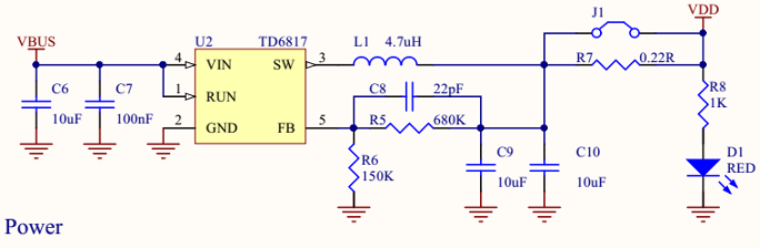
#Power Supply
VDD is decoupled by 10uF (16V) capacitor. Typical 5V to 3.3V power supply is shown in the figure below.
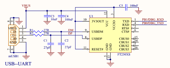
#USB-UART
The PC can be connected via USB through the USB to serial port circuit, and the module can interact through the serial port terminal. The typical circuit is shown in the figure below:
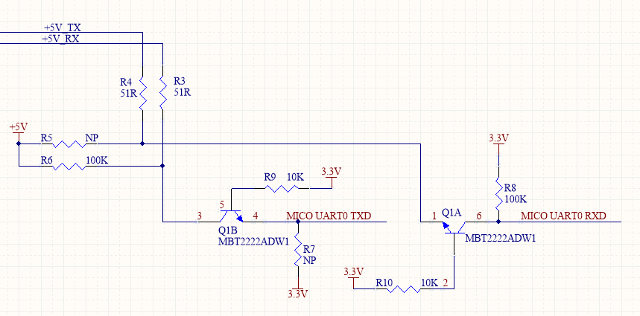
If the host uses 5V power supply and the voltage of the high-level signal of the serial port is 5V, you need to convert 5V to 3.3V before connecting to the module. Typical circuit is shown as follows.
#Intelligent Lighting
The EMW307x module can control the brightness of LED lights of various colors through the PWM pin to display various colors and warm and cold colors. PWM signals can be connected to LED of any color.
If they are connected according to the specifications shown in the figure below, you can directly use the intelligent lighting firmware provided by MXCHIP to speed up the product launch.

- If the PWM output signal is connected to an external LED lamp, it needs to be grounded through a 6K resistance; If the LED lamp is not connected, it will be suspended. When the module is running, it will automatically detect the channel of the connected LED lights to achieve the corresponding functions.
- Optional function: ADC can detect the power supply voltage and fine tune the brightness of the LED lamp.
- Optional function: GPIO control power module, which can turn off part of the power when necessary to achieve lower standby power consumption.
- Optional function: download and debug firmware using debug interface and debug serial port.
___________________________________________________________________________________________________________
END.