
# RF Test
#Introduction
In the process of product certification, it is usually necessary to evaluate the RF transceiver performance of the wireless module to determine whether it meets the certification specifications and international standards. Since the RF signal parameters and the receiving and transmitting timing cannot be kept unchanged during the normal communication of the module, the RF signal received and transmitted during the normal communication of the module is generally not directly tested during the authentication and test. The module must enter a specific RF transmission and reception mode (hereinafter referred to as ATE working mode), and set the module to receive and send specific test signals and messages by sending serial port commands on the PC for measurement by the test equipment.
#Preparation for testing
#Hardware Connection
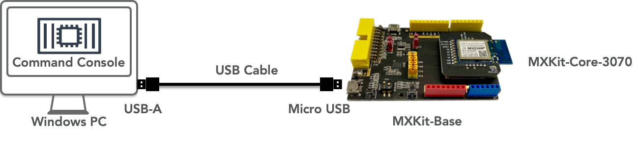
The connection diagram of the whole test system is as follows:

When the module starts, it will detect the level of Boot (P12), STATUS (P11) and EasyLink (P13) pins. When detecting the pin status, the firmware will first set the mode of P11, P12 and P13 to input pull-up. Therefore, if there is no external interference, the read IO status is High, and the default working status is Normal.
When starting, the working mode selection method of the module is shown in the following table:
Work Mode | P11(STATUS) | P12(BOOT) | P13(EASYLINK) |
Normal | Not effective | 1 | Not effective |
Bootloader | 1 | 0 | Not effective |
ATE | 1 | 0 | 0 |
QC | 0 | 0 | Not effective |
Therefore, if Boot (P12) and EasyLink (P13) are low level, the module will enter ATE mode. The module receives the control command transmitted on the PC through UART0. Therefore, the signal lines required by the module are as follows:
- Boot (P12): keep low level when the module is powered on
- EasyLink (P13): keep low level when the module is powered on
- UART1_ TXD (P2): sending signal for UART communication with PC
- UART1_ RXD (P3): receiving signal for UART communication with PC
- VDD: power supply of modules
- GND: grounding signal line of module
For the positions of the above signal and power lines on different models of modules, please refer to the data manuals of the corresponding modules.
In the following example, we choose the EMW3070 as the test module. At the same time, in order to facilitate power supply to the module and set the working mode, we install the module on the MXKit development board. The MXKit Base backplane of the MXKit can convert UART signals into USB signals, so the PC is connected to the MXKit development board through the Micro USB cable. The EMW3070 module is welded to the core board MXKit Core-3070, and then plugged into the MXKit Base backplane.
#Connect PC and Module
- Install UART to USB chip on MXKit Base backplane on PC: driver of CP2105 Download (opens new window).
- Connect PC and MXKit development board through Micro USB cable.
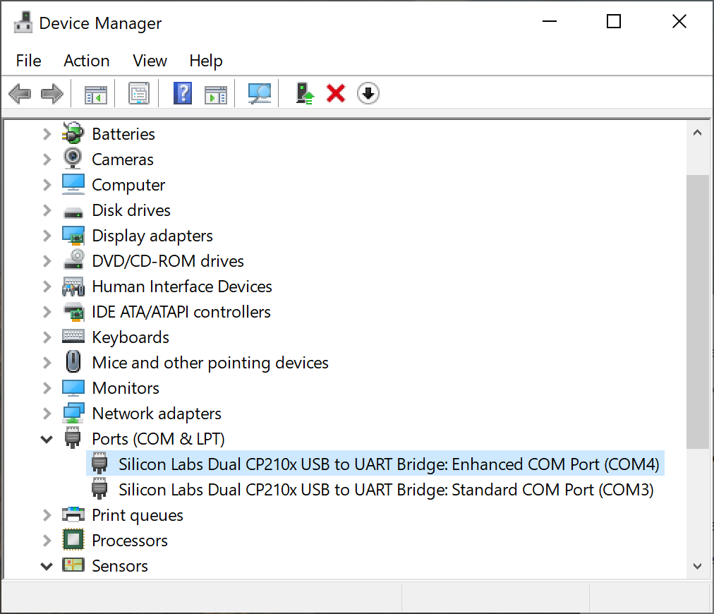
- Two virtual serial port devices can be seen on the device manager of Windows. Record the COM port number corresponding to Silicon Labs CP210x USB to UART Bridge: Enhanced COM Port. For example, in the following figure, the corresponding port number is COM4.
- Open the serial port terminal of the PC (such as SecureCRT (opens new window)), set the serial port parameter to 115200/8/n/1, and open the corresponding port, such as COM4.
#Entering ATE Working Mode
After the Boot signal and EasyLink signal of the module are grounded, the module will automatically enter the ATE working mode after the module is powered on again. The operation method on MXKit is:
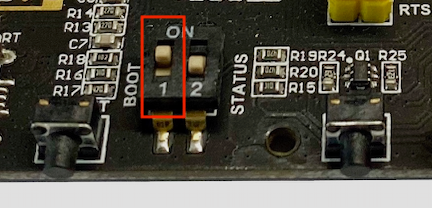
- Turn the #1 toggle switch of the dial switch on the MXKit Base board to ON.
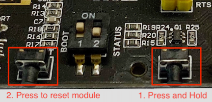
- Press and hold the ELINK button on the right, and then press the RESET button on the left. Release the module after resetting.
#Test Instructions and Examples
In the serial port terminal of PC, send the following command to test.
Enter wifi_rftest command is used for TX test, so that the calibrated value can be called.
wifi_rftest //Read calibrated value,and start test.
Examples of RF testing are as follows:
#802.11b 1Mbps modulated wave transmission test
wifi_setchn 1      //Channel switching, numbers 1 to 13 represent corresponding channels
wifi_test tx 11b 1 //Test IEEE802.11b modulation, 1Mbps rate. If test 11Mbps rate, input 11
wifi_test tx stop  //Stop modulated wave transmission
#802.11g 6Mbps modulated wave transmission test
wifi_setchn 1       //Channel switching, numbers 1 to 13 represent corresponding channels
wifi_test tx 11g 6  //Test IEEE802.11g modulation,6Mbps rate,If test 54Mbps rate,input 54
wifi_test tx stop   //Stop modulated wave transmission
#802.11n HT20 MCS0 modulated wave transmission test
wifi_setchn 1      //Channel switching, numbers 1 to 13 represent corresponding channels
wifi_test tx 11n 0 //Test IEEE802.11n modulation,HT20 bandwidth, mcs0 rate. If test MCS7 rate,input 7
wifi_test tx stop  //Stop modulated wave transmission
#Single carrier transmission
wifi_setchn 1 //Channel switching, numbers 1 to 13 represent corresponding channels
wifi_stone //Start single carrier transmission
wifi_exit_stone  //Stop single carrier transmission test
#Duty Circle Adjustment
wifi_setduty 90 //Set 90% duty circle
wifi_setchn 1 //Channel switching, numbers 1 to 13 indicate the corresponding channel
wifi_test tx 11g 6 //Test IEEE 802.11g 6Mbps, If test 54M rate,input 54,Other formats and rates operate the same way
#Receiving Sensitivity Test
wifi_setchn 1 //RX test channel
wifi_test rx 5 //RX after 5 seconds to count
Note:
You must first finish wifi_test rx 5 command and then the instrument can send packet, otherwise the packet reception will be incomplete. During the test, the packet reception delay time can be modified appropriately according to the actual situation.