
# Flash Burning
The ASR5502A(MX1270) flash used in the module can be programmed in a variety of ways to burn firmware with specific functions.
The application scenarios and restrictions of various burning methods are as follows:
Method | Interface | Communication Pin | Enter burn mode | Preparation | ||||
P10 | P14 | P15 | P16 | P12 | ||||
Simulation Debugger | SWD | P4,P5 | - | - | - | - | - | Development environment and JTAG debugger |
Bootloader Mode | UART0/UART1 | P0,P1 or P2,P3 | 0 | 0 | 0 | 0 | 0 | Flash Preburn Bootloader |
BAT Burning System | SWD | P4,P5 | - | - | - | - | - | BAT Burning System |
Offline Burner | Flash SPI | P0,P1,P2,P3 | 1 | 0 | 0 | 1 | - | Offline Burner |
Note: P10, P14, P15 and P16 are powered on at the default low level, and P12 is powered on at the default high level.
The application scenarios of each burning method are as follows:
- Simulation debugger: burning in the development and debugging stage of modules
- Bootloader mode: after the module is welded to the product, the module is burned for the second time. It is usually used in the development and debugging phase of user products.
- BAT burning system: burn the module twice on the production line of the module or product, and it can be used to burn the unique ID of the equipment.
- Offline burner: burning single firmware in batch during module production.
In conclusion, in the development phase, it is recommended to use the simulation debugger or Bootloader mode for burning. In the production stage, it is recommended to use the BAT burning system for burning. On the user's motherboard, it is recommended to lead P4 and P5 as test burning points to facilitate development and production.
#Burn By Simulation Debugger
When using the MXOS system to develop module firmware, you can directly burn the generated firmware to the module through the compilation command in the development environment. Please refer to relevant documents for the construction of MXOS development environment. The hardware emulator usually selects JLink, and the connection method is as follows:

Add the download parameter to the compile command to download the currently compiled firmware. Because the development environment needs to be installed, it is not suitable for batch factory burning of modules.
For example, compile the Helloworld application and execute the command:
mxos make helloworld@mx1270 download
The command running results are as follows:
Making config file for first time
processing components: helloworld mx1270 MXOS
……
Downloading applcation, size: 443512 bytes...
#################################################################################################################################################################################################################### 100%  433 KiB   8.0 KiB/s   18 s
Build complete
Making .gdbinit
Making .openocd_cfg
If the pre burned Bootloader in the module is damaged, just add the total parameter in the command to re burn the Bootloader.
mxos make helloworld@mx1270 total download
#Burn By Serial Port
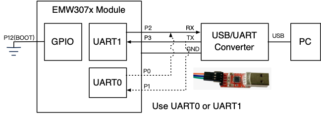
After entering the Bootloader, the processor will print menus from UART0 and UART1, and monitor these two serial ports. If any serial port inputs a burning command, the burning data can be transmitted through this serial port. The steps for burning the serial terminal software using SecurtCRT are as follows:
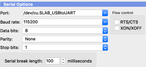
- Connect P0 (UART0_TX), P1 (UART0_RX), P2 (UART1_TX), P3 (UART1_RX) of the module with the serial port cable. USB to serial port device is usually used for transfer on PC. Set the serial port parameters on SecurtCRT: baud rate 921600, 8 data bits, no parity, and 1 stop bit.
Serial Part Connection Picture
Serial options of SecurtCRT
- Refer to the module data manual to enter the module's Bootloader mode (P10, P14, P15 and P16 are grounded or suspended, and P12 is grounded and powered on). If you enter the Bootloader mode correctly, the following information will be printed on the SecurtCRT:
MX1270 bootloader v1.1.0 built by SnowYang at Jun 28 2019 10:19:16
 - input "help" for more information.
- Enter the write command on SecurtCRT and send the firmware through the Ymodem protocol (click Transfer ->Send Ymodem). 0xA000 is the starting address of the application.
$ write 0xA000
- Wait for the transmission to complete.
Waiting for the file to be sent ... (press 'a' to abort)
CCCCCCCCCCCCCCCCCCCCCCCCCCCCCCCCCCCCCCCCCCCCCCCC
Starting ymodem transfer.  Press Ctrl+C to cancel.
Transferring /Users/william/Develop/mxos-program/mxos-demos/build/helloworld@mx1270/binary/helloworld@mx1270.bin...
  100%     433 KB       9 KB/sec    00:00:48       0 Errors

Programming Completed Successfully!
List of commands supported by bootloader :
Command | Description |
help | Display the list of commands supported by bootloader |
read [address] [length] | Read data in Flash and output them through Ymodem protocol. [address] is the address offset of the data in Flash, and [length] is the length of the read data. |
write [address] | Write data to the [address] offset address of Flash through Ymodem protocol |
erase [address] [length] | Erase the space on the Flash starting from [address] with a length of [length] |
boot [address] | Firmware stored on [address] in boot Flash |
reboot | Reboot system again |
dump [address] [length] | Read and display the contents of [length] starting from [address] in the chip storage space, usually used to obtain the contents stored in peripheral registers and RAM. To read the contents in Flash, note that the starting address of Flash is 0x10000000. |
version | Get the version of the bootloader |
Note:[address] point to the internal address of Flash, starting from 0x0 address.
#Burn by Offline Burner
The offline programmer (model: MXFlash) is a simple and easy to use burning tool. The burned firmware is stored in the internal auxiliary memory of the programmer. As long as it is correctly connected to the module, the burning can be started automatically. It does not require complicated installation process and is suitable for batch burning modules in the factory.
MXFlasher Burner
#Hardware Connection and Burning
The hardware connection method of using MXFlash for burning is shown in the figure below. MXFlash uses USB to supply power for module.
MXFlasher Hardware Connection

All MXKit Core 307x core boards lead out burning interfaces, which can be directly connected to MXFlash.
The burning steps are as follows:
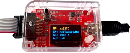
1. Use USB cable to supply power to MXFlash, and MXFlash starts. The screen displays the burner configuration information. Press the key on MXFlash, and the screen will display "Insert module".
- HW: The burned target processor must be confirmed as "MX1270". Otherwise, it cannot be burned correctly. Please refer to "MXFlasher Settings" for reconfiguration.
- SW: The name of the burned firmware. Please refer to "MXFlasher Settings" for reconfiguration
- SZ: burned firmware size
- AD: Burn target address. Please refer to "MXFlasher Settings" for reconfiguration
MXFlasher Start and enter burn mode

2. Connect MXFlash and module correctly. If you use the MXKit Core 307x core board, you only need to use a 10 core connection burning interface.
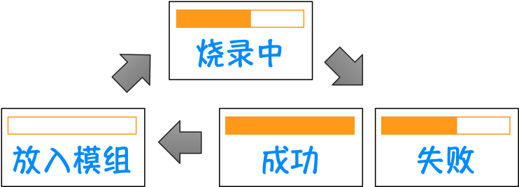
3. The progress bar and "Burning" will be displayed on the screen, and the LED light starts to flash. Wait for the burning to complete.
- After burning, the screen will display "Success" and the LED will display green.
- If an error occurs, the screen will display "Failed" and the LED will display red.
- LCD display during MXFlash burning
MXFlasher LCD display during burning
- Connect the next module to automatically start the next burning.
#MXFlasher Settings
Set MXFlash to enter the setting mode through the following steps
1. Connect MXFlash to PC through USB cable, wait for MXFlash to start, and the screen will display the burner configuration information.
2. Press and hold the button on MXFlasher until the LED light shows red and the colleague displays the "gear" pattern on the screen.
3. A USB disk named "MXCHIP" can be seen on the PC. The USB disk contains the following files:
- README.TXT: simple operation manual
- Various bin files: firmware to be burned
- config.txt: Burner configuration file with the following contents:
/**
* platform://The configured burning target chip model, set as mx1270
* filename://The name of the binary file burned, and the file must be saved in the USB flash disk
* address: //Start address of burning
*/
{
     "platform": "mx1270",
     "filename": "all.bin",
     "address": "0x00",
}
Configuration example: Burn at_cmd@mx1280.all.bin to 0x00 address.
- Copy Firmware“ at_cmd@mx1280.all.bin " to USB disk.
- Open config.txt, modify it as follows, and save it.
{
     "platform": "mx1270",
     "filename": "at_cmd@mx1280.all.bin",
     "address": "0x00",
}
3. After configuration, set MXFlasher to enter the burning mode
- (1) Press the key on MXFlash, the burner will enter the burning mode, and the current configuration information will be displayed on the display, and the LED light will go out.
- (2) Press the key on MXFlash, and the screen will display "Insert module".
- (3) After connecting the module to be burned as shown in Figure 14, the burning starts automatically. "Burning" is displayed on the screen, and "Success" is displayed after completion
- (4) Connect the next module to automatically start the next burning.
#Burn by BAT
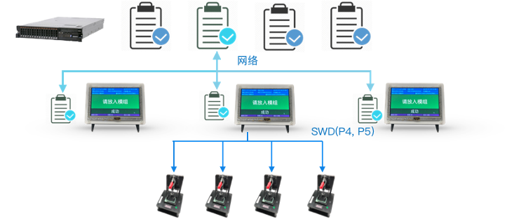
BAT is a production tool for factory batch burning launched by MXCHIP. It can not only burn firmware, but also burn unique IDs for each module, such as cloud service verification code, security key, certificate, token, etc. BAT system adopts server client architecture. Firmware and ID can be imported in batches on the server to create production tasks and uniformly manage the production system. The client synchronizes production tasks from the server, and one client can burn four modules at the same time. The client can also interface with the automatic systems such as the feeding machine and the mechanical arm to achieve fully automatic production.
For the usage of the BAT system, please refer to the relevant usage documents of the BAT system. EMW307x module interacts with BAT system through SWD interface. The following is the application block diagram of BAT system:
BAT Burning System
—————————————————————————————————————————————
END.