
# RF Test
#Introduction
In the process of product certification, it is usually necessary to evaluate the RF transceiver performance of the wireless module to determine whether it meets the certification specifications and international standards. Since the RF signal parameters and the receiving and transmitting timing cannot be kept unchanged during the normal communication of the module, the RF signal received and transmitted during the normal communication of the module is generally not directly tested during the authentication and test. The module must enter a specific RF transmission and reception mode (hereinafter referred to as ATE working mode), and set the module to receive and send specific test signals and messages by sending serial port commands on the PC for measurement by the test equipment.
#Hardware Connection
The connection diagram of the whole test system is as follows:
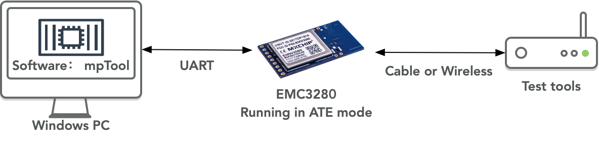
The PC is connected to the module running in ATE mode through the serial port, and controls the module to send and receive RF signals of various parameters through UART command. The test instrument can receive the signal of the module through the antenna, or directly connect with the antenna interface of the module through the RF cable, so as to comprehensively test and evaluate the RF performance of the module.
Send and receive UART commands on PC through testing control software:
- Test the control software of Wi Fi signal::📎mptool_2V0.rar
- Test the control software of Bluetooth signal::📎Bluetooth_MP_Kit_Setup_Package.zip
When the module starts, it will detect the level of the Boot signal and EasyLink pins. If both pins are low, the module will enter the ATE mode. The module passes UART_ LOG receives control instructions transmitted on PC. Therefore, the signal lines required by the module are as follows:
● Boot: keep low level when the module is powered on
● Status: maintain high level when the module is powered on (default)
● UART_ LOG_ TXD: receiving signal for UART communication with PC
● UART_ LOG_ RXD: sending signal for UART communication with PC
● VDD: power supply of modules
● GND: grounding signal line of module
For the positions of the above signal and power lines on different models of modules, please refer to the data manuals of the corresponding modules. For EMC3280, Pin19 (boot) is grounded (pulled down), and Pin21 (UART_LOG_TXD)&Pin22 (UART_LOG_RXD) is connected to the UART of the PC.
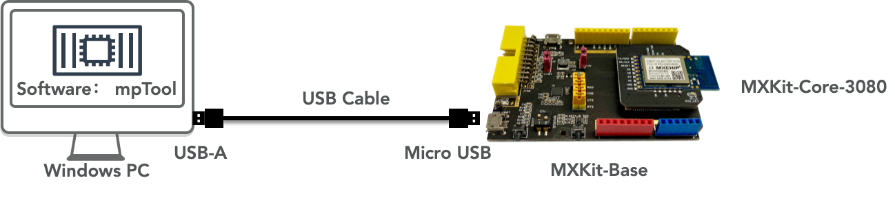
In the following example, we choose EMC3280 as the test module. At the same time, in order to facilitate the power supply to the module and the setting of the working mode, we install the module on the MXKit development board. The MXKit Base backplane of the MXKit can convert UART signals into USB signals, so the PC is connected to the MXKit development board through the Micro USB cable. The EMW3280 module is welded to the core board MXKit Core-3080, and then plugged into the MXKit Base backplane.
#Preparation for Testing
#Connect PC and Module
- Install the UART to USB chip on the MXKit Base backplane on the PC: CP2105 Driver (opens new window).
- Connect PC and MXKit development board through Micro USB cable.
- Two virtual serial port devices can be seen on the device manager of Windows. Record the COM port number corresponding to Silicon Labs CP210x USB to UART Bridge: Enhanced COM Port. For example, in the following figure, the corresponding port number is COM4.

#Module Enters the ATE working mode
After the boot signal of the module is grounded and the module is powered on again, the module will automatically enter the ATE working mode. The operation method on MXKit is:
1. Turn the 1 # toggle switch of the dial switch on the MXKit Base board to ON.
2. Press the RESET button on the left. Release the module after resetting.

#Wi-Fi Test Method
#mpTool introuction
- Download mpTool:📎mptool_2V0.rar,After decompression, run the UI_ mptool.exe.
- Complete the test preparation.
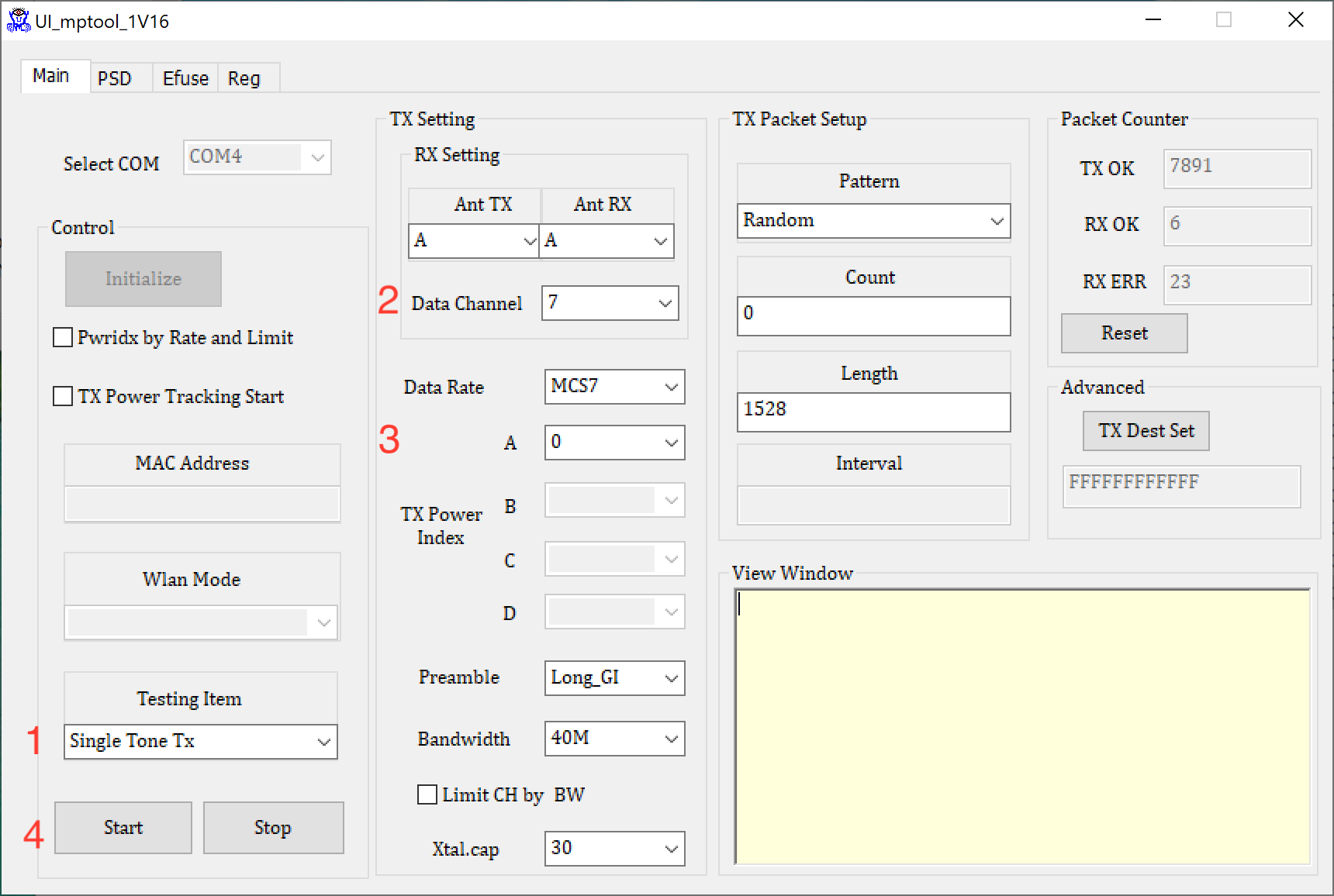
- In the Main tab, select the serial port number recorded in the step of "connecting PC and module" from the drop-down menu of select COM. In this example, COM4.
- Click Initialize button to complete initialization. If initialization fails, the View Window on the right side of the software will display the cause of the error. After success, other controls in the software will be turned on.

The mpTool software is divided into four labels, namely Main, PSD, Efuse and Reg.
In the Main window, you can set RF transceiver parameters and modes, and start the transceiver test. Other windows are used for module production, and users do not need to operate. If the functions of these labels are used without authorization, it is likely to damage the calibration parameters of the module produced in the factory, and cause permanent damage to the module that cannot be repaired.

The functions of each control in the Main tab window are as follows:
Select COM: select the serial port number for communication between PC and module
Control: including various control functions
Initialize: initialize the serial port and the module to be tested.
Pwridx by Rate and Limit: When it is selected, the software reads the initial value of the parameter from the Efuse of the module, and limits the antenna transmission power to a certain extent, which is displayed in the TX Power Index and cannot be modified. If it is not selected, the user can adjust the value in the TX Power Index to increase or decrease the transmission power.
TX Power Tracking Start: start the temperature compensation function, usually not.
MAC Address, Wlan Mode: optional.
Testing Item: Select the test items, as follows:
- Packet TX: used to test RF transmission performance, such as power, EVM and frequency offset.
- Continuous TX: used to test transmission power or maximum power consumption of test modules in FCC/CE/CMCC/CTA certification.
- Single Tone TX: used to test frequency offset.
- Carrier Suppression TX: used for 802.11b only.
- Packet RX (All), Packet RX (Filtered): receiving test, which can be used to test the receiving sensitivity and bit error rate of the module.
Start/Stop: start and stop the test item selected in "Testing Item".
TX Setting and RX Setting: set RF parameters of receiving and sending.
- Ant TX and Ant RX: For this series of modules, fixed option A.
- Data Channel: Select the radio frequency band for RF transceiver.
- Data Rate: modulation mode and data transmission rate.
- TX Power Index: antenna transmission power (only A antenna can be set). The module cannot set the RF signal with a fixed output power, and it can only be adjusted based on the current transmission power. The transmission power will increase/decrease by 0.5dBm for each increase/decrease of 1 in the Power Index. The initial value of TX Power Index is saved in Efuse, and is calibrated by MXCHIP during module production. It conforms to the parameters in the data manual, ensures performance and meets the requirements of certification standards.
- Preamble: Set the preamble mode of the message, Long is optional_ GI and Short_ GI.
- Bandwidth: RF transceiver bandwidth, 20MHz or 40MHz.
- Xtal.cap: calibration value of crystal oscillator, which can be used to adjust RF frequency offset.
TX Packet Setup: set message sending parameters.
- Pattern: set the type of TX message.
- Count: number of package sent.
- Length: length of each package.
- Interval: not adjustable.
Packet counter: display the number of packets sent, received and received with errors
- Reset: Restore the quantity to 0
View Window: Software Log output window
#Wi-Fi Test Demo
#Signaling Mode Sending Test
#Read factory default parameters

- Choose --> Pwridx by Rate and Limit,read factory parameter from Efuse.
- Choose -->TX test item -->Packet TX.
- Choose RF channel.
- Select modulation mode and data rate.
- Select bandwidth.
- Start test.
#Define Parameters for Sending Data Package

- Do not select Pwridx by Rate and Limit
- Select TX test item: Packet TX
- Select RF channel
- Select modulation mode and data rate
- Set the transmission power. Under different modulation modes and rates, the transmission power settings are shown in the following table. Increase or decrease on this basis
802.11b | 802.11g | 802.11n | |||
1M | 11M | 6M | 54M | MCS0 | MCS7 |
35 | 35 | 46 | 44 | 45 | 42 |
- Choose Bandwidth
- Select frequency calibration parameters
- Start test
#Single Tone Sending Package Test
- Choose TX Testing Item:Single Tone TX.
- Choose RF Channel.
- Set the transmit power parameter to 0.
- Start Test.
#Receiving Test

- Choose RX Testing Item:Packet Rx(All).
- Choose RF channel.
- Start test.
- Check the number of packets received.
#Bluetooth Test Method
#Enter Bluetooth Test Mode
The wiring mode is the same as that of Wi-Fi test. After testing Wi-Fi, mptool must be turned off to release the serial port.
- Open the serial port terminal (take SecureCRT as an example)
Input the following three commands in the terminal:
ATM2=bt_ power,on
ATM2=gnt_ bt,bt
ATM2=bridge
In the terminal, you will see the following information printed, indicating that you have entered the Bluetooth ATE mode.
<img width="560" alt="" src="/img/1585825393186-4a6c70d6-53ce-4760-9af9-1f107840af4a.png"></img>
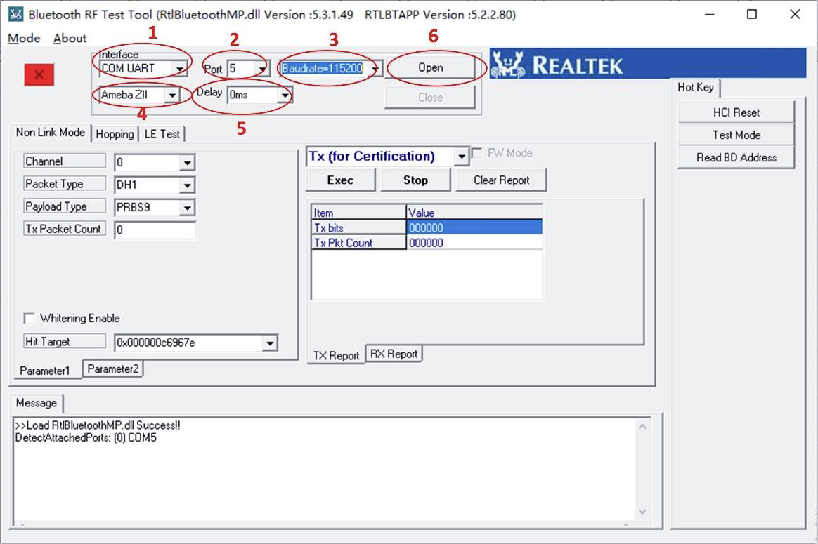
Open Bluetooth MP Kit Setup Package ,and find“RTLBTAPP.exe”to open it.
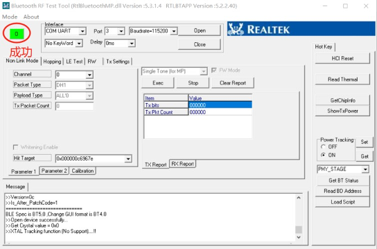
Set in the following order, and finally click "Open" to initialize. After success, the upper left corner will turn green, as shown below.
#Bluetooth Sending Test
Open“LE Test”Menu and set Tx mode, channel, number of packets, rate, etc. in this interface. After setting, click "Start" to start signal output. As indicated by the arrow below.
<img width="643" alt="" src="/img/1585825502124-98afdf47-0050-4b32-9ea0-3a973db0aa72.png"></img>
#Bluetooth Receiving Test
Open“LE Test”Menu and set Rx mode, channel, number of packets, rate, etc. in this interface. After setting, click "Start" to start signal output. As indicated by the arrow below.
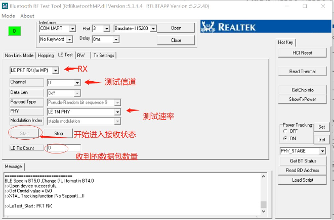
Click "Stop" after the test instrument is sent out, and the number of packets received will be displayed at "LE Rx Count". After clearing, click "Start" again to enter the next test.
#Connect Module and RF Testing Instrument
There are two methods for the RF test instrument to detect the RF signal sent module.
- Wireless reception with 2.4GHz antenna.
- Receive deirectly after connecting the transmission wire with the antenna interface of module. If module uses PCB on-board antenna, disconnect the PCB of the module.
Follow the following test stetps:
1.  <span class="ne-text">Remove the 0 ohm resistance between the chip and the antenna on the module.</span>

<span class="ne-text">     </span><img width="245" alt="" src="/img/1582878943267-bf5df111-cbe2-46dd-89a1-1e1970d08d6f.png"></img>

<span class="ne-text">b. Weld the transmission wire to the antenna test point on the back fo the module, and connect the other end of the transmission wire to the test instrument.</span>

<span class="ne-text">     </span><img width="427" alt="" src="/img/1582878392541-1cbc9ee0-0f69-4b81-92bb-4b6f7b310305.png"></img>
#Appendix 1: Wi Fi ATE Serial Port Instruction
mptool interacts with the module to be tested through serial port instruments.Developers can develop customized testing systems according to these instructions.
#Command List
#Start MP mode
After execute the command, Wi-Fi driver will stop tranmitting data, and enter to MP mode.
iwpriv mp_start
#Stop MP mode
After execute the command, Wi-Fi driver will stop message output started by other command. But the system can enter the normal Wi Fi connection mode only after it is restarted.
iwpriv mp_stop
#Set Tx rate
Set Tx message data transmission rate.
iwpriv mp_rate rate
rate: data transmission rate. 2 = 1M, 4 = 2M, 11 = 5.5M, …, 108 = 54M, 128 = MCS0, 129 = MCS1, …, 142 = MCS15
#Set operational channel
Set the working frequency band for sending and receiving messages.
iwpriv mp_channel channel
channel: frequency band for sending and receiving messages.
#Set operational bandwidth
Set the bandwidth for sending and receiving data packets and the Guard Interval for transmitting MCS messages. If no parameter is provided, the default setting is 20MHz bandwidth, and long GI is used for transmission.
iwpriv mp_bandwidth 40M=40m, shortGI=sgi
40m: set bandwidth,1=40M mode,0=20M mode.
sgi: set mode of GI,1=Short GI,0=long GI.
#Set Tx power
Set transmission power of path A and B. If no parameters are provided, the preset parameters in Flash are used.
iwpriv mp_txpower patha=x,pathb=y
x: transmission power of path A.
y: transmission power of path B.
#Set antenna for Tx
Set antenna used for transmission.
iwpriv mp_ant_tx ant
ant: antenna used for transmission. a=antenna A,b=antenna B,ab=antenna A and B。
#Set antenna for Rx
Set antenna used for reception.
iwpriv mp_ant_rx ant
ant: antenna used for reception. a=antenna A,b=antenna B,ab=antenna A and B.
#Start air Rx mode
The command is used for wireless reception test. Use the stard command to start package reception, the stop command to stop counting and display the statistics of correct and error messages. Use the phy command to display number of packets received by the RF physical layer,CRC errors, and failure alarms.
iwpriv mp_arx start/stop/phy
start: start rececption.
stop: stop counting and display statistics.
phy: display number of packets received by the RF physical layer,CRC errors, and failure alarms.
#Start continuous Tx mode
The command is used for continous sending test. Use the time command to set the sending time, and the count command to set the number of packets to be sent.
- If the time and the count are not set, the continuous sending mode will be started.
- If the background mode is not set, any character input can stop sending.
- If the cs mode is not set,the carrier suppression signal is tranmitted.
- Use the stone command to send single tone signal to test the frequency.
- If stone is set, the signal sent will not be a recognizable message.
- By default, hardware is used to send short duty cycle signals.
- If pkt is set,software controls the sending of packets.
iwpriv mp_ctx count=n,background,stop,pkt,cs,stone
t: set time of sending packets
n: set number of sending packets
background: set mode of backstage transmitting data
stop: stop backstage transmitting data
pkt: transmit tx packets
cs: transmit carrier suppression signal
stone: transmit single tone carrier suppression signal
#Query air Rx statistics
Used for wireless message counting. When transmitting data packets, use this command to obtain the number of transmitted messages. When receiving, this command can be used to obtain the statistics of correct and CRC error messages.
iwpriv mp_query
#Reset air Tx/Rx statistics
This command can recharge the message count. When sending, this command can reset the number of packets, and when receiving, it can reset the number of correct and CRC error messages.
iwpriv mp_reset_stats
#Command Usage Demo
#Continous Transmitting Test
iwpriv mp_start                            //enter MP mode
iwpriv mp_channel 1                        //set channel to 1 . 2, 3, 4~11 etc.
iwpriv mp_bandwidth 40M=0,shortGI=0        //set 20M mode and long GI
iwpriv mp_ant_tx a                         //select antenna A for operation
iwpriv mp_txpower patha=44,pathb=44        //set path A and path B Tx power level
iwpriv mp_rate 108                         //set OFDM data rate to 54Mbps,e x: CCK 1M = 2, CCK 5.5M = 11, KK, OFDM54M = 108 N Mode: MCS0 = 128, MCS1 = 129…..etc.
iwpriv mp_ctx background                   //start continuous Tx
iwpriv mp_ctx stop                         //stop continuous Tx
iwpriv mp_stop                             //exit MP mode
#Continuous message sending test
iwpriv mp_start                             //enter MP mode
iwpriv mp_channel 1                         //set channel to 1 . 2, 3, 4~11 etc.
iwpriv mp_bandwidth 40M=0,shortGI=0         //set 20M mode and long GI
iwpriv mp_ant_tx a                          //select antenna A for operation
iwpriv mp_txpower patha=44,pathb=44         //set path A and path B Tx power level
iwpriv mp_rate 108                          //set OFDM data rate to 54Mbps, ex: CCK 1M = 2, CCK 5.5M = 11, KK, OFDM54M = 108 N Mode: MCS0 = 128, MCS1= 129….. etc.
iwpriv mp_ctx background,pkt                //start packet continuous Tx
iwpriv mp_ctx stop                          //stop continuous Tx
#Carrier suppression test
iwpriv mp_start                               //enter MP mode
iwpriv mp_channel 1                          //set channel to 1 . 2, 3, 4~11 etc.
iwpriv mp_bandwidth 40M=0,shortGI=0         //set 20M mode and long GI
iwpriv mp_ant_tx a                           //select antenna A for operation
iwpriv mp_txpower patha=44,pathb=44         //set path A and path B Tx power level
iwpriv mp_rate 108                           //set OFDM data rate to 54Mbps,ex: CCK 1M = 2, CCK 5.5M = 11, KK, OFDM54M = 108 N Mode: MCS0 = 128, MCS1 = 129…..etc.
iwpriv mp_ctx background,cs                  //start sending carrier suppression signal
iwpriv mp_ctx stop                           //stop continuous Tx
iwpriv mp_stop
#Single Tone Signal Tranmition Test
iwpriv mp_start                              //enter MP mode
iwpriv mp_channel 1                          //set channel to 1 . 2, 3, 4~11 etc.
iwpriv mp_bandwidth 40M=0,shortGI=0         //set 20M mode and long GI
iwpriv mp_ant_tx a                           //select antenna A for operation
iwpriv mp_txpower patha=44,pathb=44         //set path A and path B Tx power level
iwpriv mp_rate 108                           //set OFDM data rate to 54Mbps,ex: CCK 1M = 2, CCK 5.5M = 11, KK, OFDM54M = 108 N Mode: MCS0 = 128, MCS1 = 129…..etc.
iwpriv mp_ctx background,stone              //start sending single tone signal
iwpriv mp_ctx stop                           //stop sending single tone signal
iwpriv mp_stop                                //exit MP mode
#Reception Test
iwpriv mp_start                               //enter MP mode
iwpriv mp_bandwidth 40M=1,shortGI=0         //set 40M mode and long GI
iwpriv mp_channel 6                          //set channel to 6
iwpriv mp_ant_rx ab                          //select all 2 antennas for operation
iwpriv mp_arx start                          //start air Rx
iwpriv mp_query                               //get the statistics
iwpriv mp_arx stop                           //stop air Rx and show the statistics
iwpriv mp_stop                                //exit MP mode
#Appendix 2:Bluetooth ATE Serial Command
In ATE mode, you can switch from Wi-Fi ATE mode to Bluetooth ATE mode by sending three commands through the debug serial port (baud rate 115200)
ATM2=bt_power,on
ATM2=gnt_bt,bt
ATM2=bridge
#Command format of Bluetooth serial port
The following serial port commands are sent in hexadecimal format.
#Start Bluetooth Sending
Example:01 1f 20 00 01 34 20 04 00 ff 00 01
Start sending data accroding to specified parameters.
01 1f 20 00 01 34 20 04 | Command Header |
00 | Channel 0(2402MHz). The channel can be changed to 0~39 Channel correspondence: 00(ch0),01(ch1),02(ch2)…0a(ch10), 0b(ch11)…0f(ch15)…13(ch19)…27(ch39) |
ff | Length of data. The data length can be set from 00 to ff. The longest ff is used by default |
00 | Package type is PRBS9, and the corresponding relationship between package types is:: 00:PRBS9 ; 01:11110000 ; 02:10101010 |
01 | BLE rate: 01=1M; 02=2M |
#Stop Bluetooth Sending
Example:01 87 fd 01 07 01 1f 20 00,Stop sending.
#Start Buletooth Receiving
Example:01 33 20 03 00 01 01
Start receiving data accroding to specified parameters.
01 33 20 03 | Command Header |
00 | Channel 0(2402MHz). The channel can be changed to 0~390~39 Channel correspondence: 00(ch0),01(ch1),02(ch2)…0a(ch10),0b(ch11)…0f(ch15)…13(ch19)…27(ch39) |
01 | BLE rate: 01=1M, 02=2M |
01 | Command End |
#Stop Bluetooth Receiving
Example:04 0e 04 02 87 fd 01,Stop Receiving.
#The module returns the packet receiving result
Example:04 0e 06 02 1f 20 00 cd 03
04 0e 06 02 1f 20 00 | Command Header |
cd 03 | The number of packets received by the module, small end format, with the low bit first and the high bit last, such as cd 03=1973 |
#Command Usage Demo
#BLE Sending Test Demo
- Sending Command:01 1f 20 00 01 34 20 04 00 ff 00 01
Transmit as channel 0, data length is ff, packet type is PRBS9, and BLE 1M
- Send command: 01 1f 20 00 01 34 20 04 00 ff 01 02
Transmit with channel 0, data length ff, packet type 11110000, BLE 2M
#BLE Receiving Test Demo
- Sending instruction: 01 33 20 03 00 01 01
Enter channel 0, rate 1Mbps receiving status
- Send command: 04 0e 04 02 87 fd 01
Stop receiving packets
- Receive command: 04 0e 06 02 1f 20 00 cd 03
Calculate the number of packets received. The last two bytes represent the number of packets received (hexadecimal, with the high bit in the back (such as 03) and the low bit in the front (such as cd)). 03cd is converted to decimal number 1973. The application program needs to automatically convert the received data into decimal numbers and display them.
————————————————————————————————————————————
End.