
# EMW3090 Series Firmware Download
#1. Pin Description
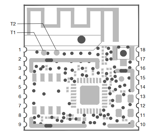
Pin | Function | Note |
PIN1 | VDD | 3.3V Power |
PIN18 | VSS | Ground |
PIN7 | debug-TX | Print log. |
PIN8 | debug-RX | send cli command. |
PIN 12 | UART TX | Used for communication with boards and bootloader mode. |
PIN 11 | UART RX | |
T1 | SWDIO | jlink-swd burnding. |
T2 | SWCLK | jlink-swd burning. |
PIN 17 | BOOT | trigger boot mode. |
PIN 14 | easylink | Trigger together with the boot pin to enter into ATE mode. |
#2. Burning in bootloader mode
#2.1. Burning Method of all.bin
Enter bootloader mode through the user serial port by using the command 4- dev 1.
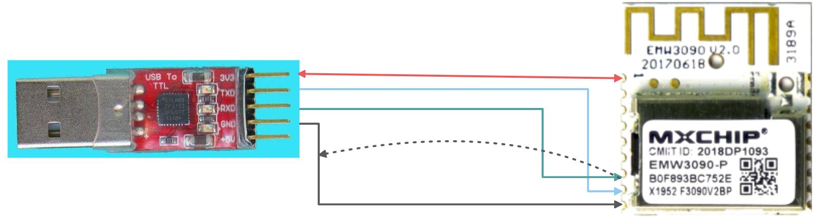
1. Power on the module and connect the user's serial port to the PC USB interface through the "TTL to USB module", and find the corresponding COM port number in the device manager, such as COM1;

2.Open the serial port debugging software tool - SecureCRT, connect to the user's serial port COM1, with a baud rate of 921600bps;

3.Pull the BOOT pin low, then Reset low. After restarting, the user's serial port outputs bootloader information, and then enters the command: 4- dev 1- start 0x0- end 0x160000, and then returns, as shown in the following figure:

4.Select the all. bin firmware file to burn, open the Transfer -->Send Ymodem interface, and select the firmware file to burn in the PC directory, as shown in the following figure:

5.After confirmation, start burning, and the completion interface is as follows:

#2.2. Burning method of ota.bin
Burning Command:1
If the module was originally a micro version firmware and needs to be burned to an mxos version firmware, it must be burned to all. bin using 4- dev 1.
The reverse is also true, in order to burn the firmware of the mxos version into the firmware of the micro version, it is necessary to use 4- dev 1 to burn all. bin.
#3. Burning Method of Image-tool
#3.1. Wiring Diagram
#3.2. Software Download
#3.3. Software Description
This software uses the module log serial port for information updates, and can burn different bin files by configuring different addresses.
- Trigger method: Short circuit the module debug TX and GND to power the module back on;
- If the module cannot start, you can use this software to update it.
#3.4. Software Configuration
- Only the all. bin file can have only the BOOT option checked.

#3.5. Successful identification

#3.6. Finish Burning

#4. Burning all.bin through Mflash
#4.1. Environmental construction
Refer to: Common Tools and Documents.
#4.2. Wiring Diagram
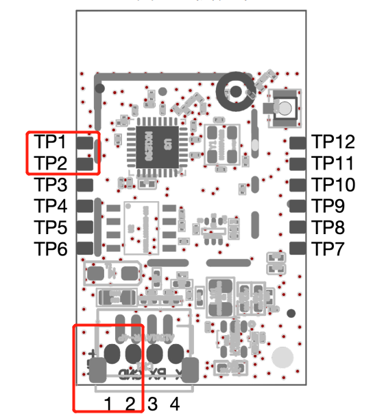
EMW5080模块
- TP1:SWD-CLK
- TP2:SWD-DIO
- 1:VCC-5V
- 2:GND
#4.3. Software Description

#5. QC Test
Triggered by lowering the boot pin or user serial port input # # #, baud rate: 921600bps.
#Update Record
Version | Description | Date |
V1.1 | Adjust Format | 2021.9.13 |
V1.2 | Add 5080 module pin diagram | 2021.9.17 |
V1.3 | Add wiring diagram | 2022.1.24 |