# EMC3380 Firmware Download
#1. Description of Working Mode
Module Working Mode | PB1(BOOT) -Pin37 | PB23(status) -Pin5 | PA7(LOG-TX) -PIN19 |
Normal | 1 | No Detection | 1 |
ATE | 0 | 1 | No Detection |
QC | 0 | 0 | No Detection |
ImageTool-download | 1 | 1 | 0 |
jlink-download | No Detection | No Detection | No Detection |
#2. Fixture Diagram
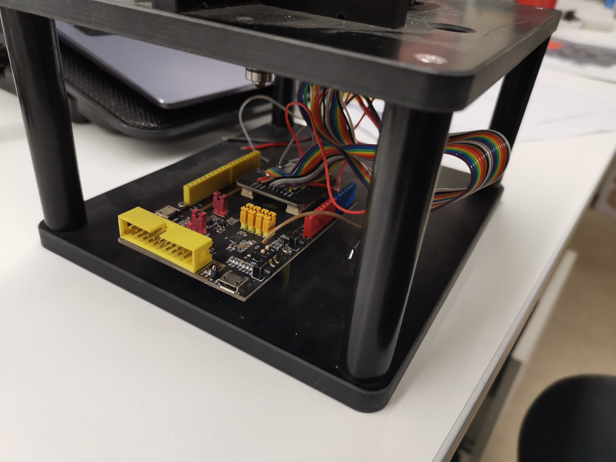
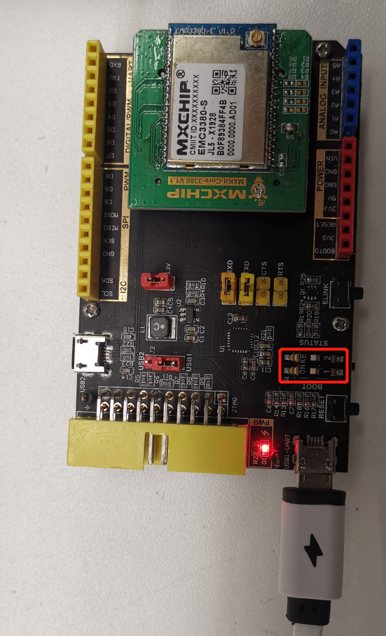
Explanation:
- The upper dial button in the red box is status, and the lower dial button is boot. The dial button on the left indicates a low pull and on the right indicates a high pull.
- Virtual two serial ports on the computer through a USB cable, corresponding to the user serial port and debug serial port of the module.
#3. Burning Instruction
#3.1. Jlink Burning
#3.1.1. Wiring Diagram
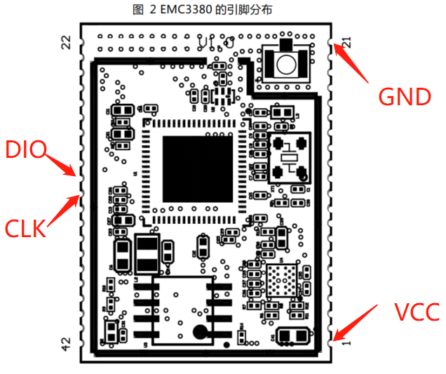
#3.1.2. Software and Configuration Reference
Get more help,please refer to: Common Tools and Documents.
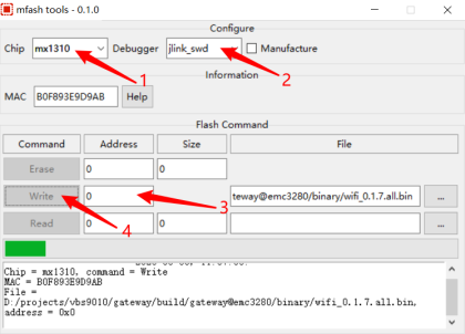
#3.1.3. Software Usage
Jlink burning tool combined with mflash software.
#3.2. Image-tool Burning
#3.2.1. Wiring Diagram
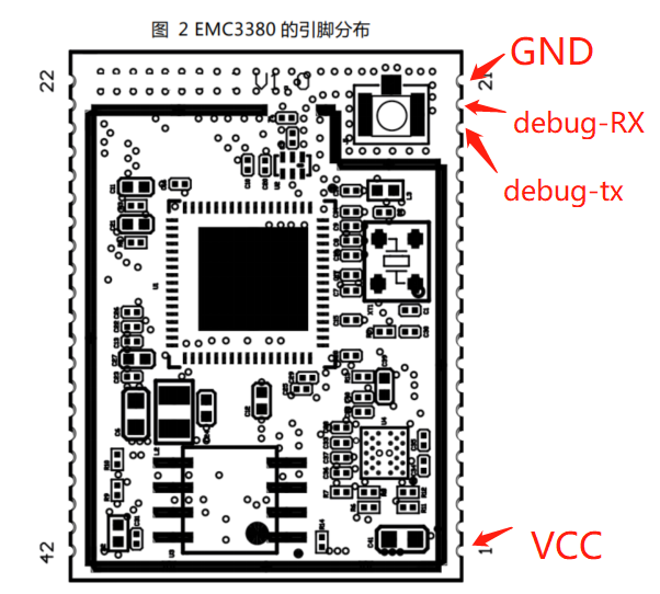
#3.2.1 Software Download
Image-tool donwload: 📎MX131x烧录工具.zip
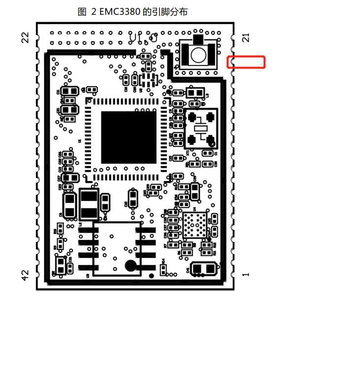
#3.2.2 Trigger Method
1. Debug TX pull down and power on
2. Restore the connection between debug TX and TTL small board
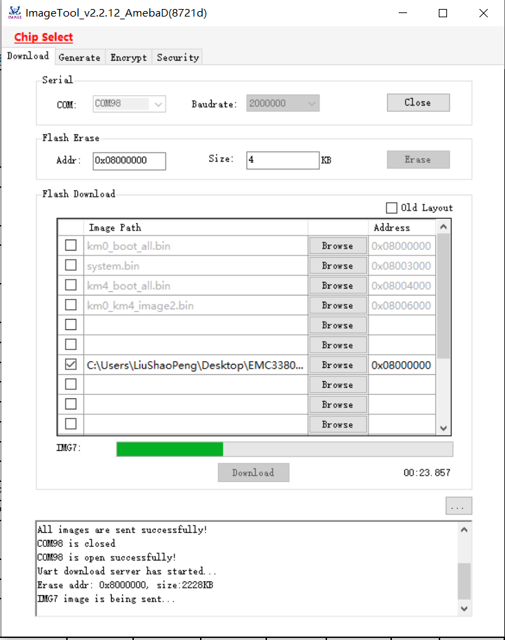
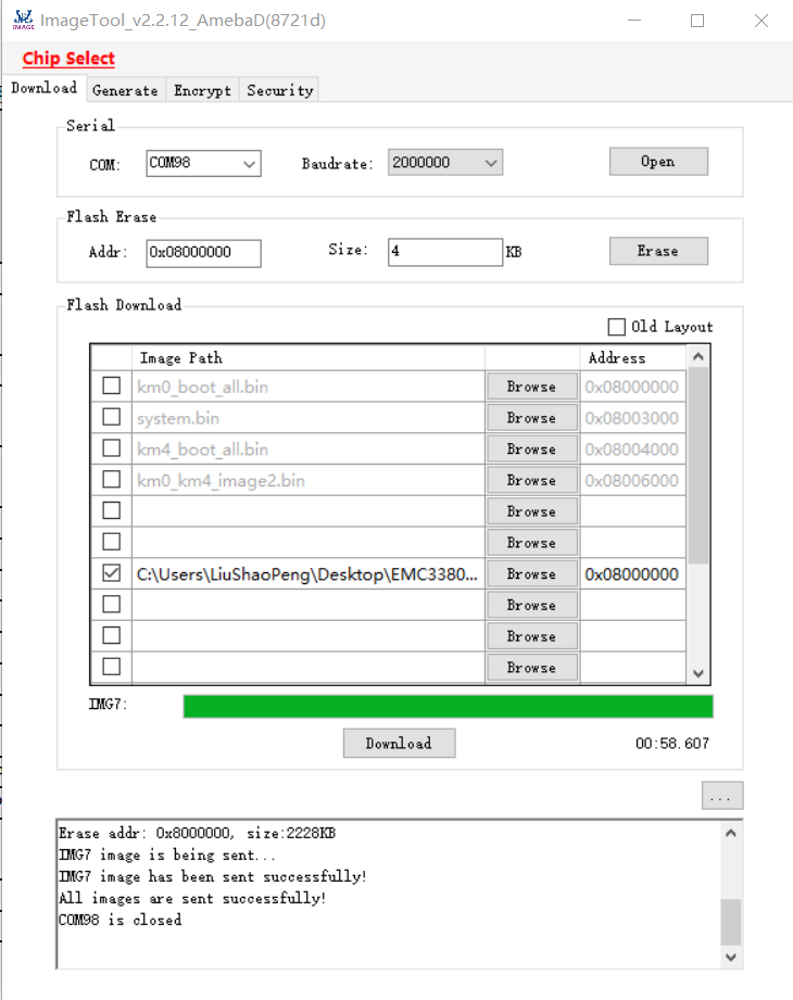
#3.2.3 Buning Interface
- Select Chip 8721D
#4. QC
#4.1. Wiring Diagram
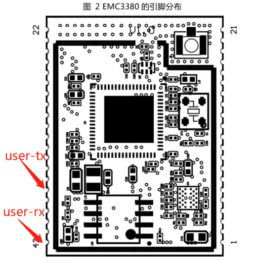
#4.2. Confirm firmware
By comparing the printed information, it is used to determine whether the firmware burned is correct and whether the RF is working properly.
#4.3. Trigger Mothod
Pull down the Boot pin and Status pin, with a baud rate of 115200 for both user and debug serial ports.
#4.4. Log Demo
==== MXCHIP Manufacture Test ====
Serial Number: 0000.0000.A225
App CRC: 7DE7
Bootloader Verson: Bootloader
Library Version: v6.0-20-g3dd9912
APP Version: MXOS OS at_basic_2.2.5, build at 18:59:33 Feb 19 2020
Driver: mx3380-x
MAC: B0-F8-93-84-FF-4B
Local Bluetooth Address: B0-F8-93-00-A8-67
BLE scan complete
  ADDR: 7b:9c:fc:a2:f0:c3, RSSI: -100
  ADDR: 76:da:11:14:c5:47, RSSI: -104
Scan AP Success:
  SSID: mxchip-guest, RSSI: -66
  SSID: mxchip-office, RSSI: -67
  SSID: mxchip-office, RSSI: -74
  SSID: mxchip-guest, RSSI: -78
  SSID: Tenda_908020_5G, RSSI: -81
  SSID: mxchip-office, RSSI: -82
  SSID: mxchip-guest, RSSI: -82
  SSID: snowyang_5G, RSSI: -86
  SSID: test_zhy, RSSI: -92
  SSID: ABCDEFG, RSSI: -94
  SSID: Xiaomi_bat111, RSSI: -94
  SSID: mxchip-office, RSSI: -96
  SSID: , RSSI: -97
  SSID: mxchip-guest, RSSI: -98
  SSID: Tenda_908020, RSSI: -107
  SSID: , RSSI: -108
  SSID: mxchip-office, RSSI: -109
  SSID: mxchip-guest, RSSI: -109
  SSID: mxchip-guest, RSSI: -110
  SSID: mxchip-office, RSSI: -111
  SSID: , RSSI: -111
#5. ATE Mode
ATE mode is only used during module production testing and is not described here.
#Update Record
Version | Update | Date |
V1.0 | Initial Version | 2020/10/20 |
V1.1 | Added working mode instructions | 2021/2/25 |
V1.2 | Add wiring diagram | 2021/12/13 |
